Storage Interface Chipset:
- 6 x SATA 6Gb/s connectors
* Refer to "1-7 Internal Connectors," for the installation notices for the M.2 and SATA
connectors.
Intel
®
Optane
™
Memory Ready
* System Acceleration with Intel
®
Optane
™
Memory enabled on the M2A_32G connector
only.
USB Chipset:
- 1 x USB 3.1 Gen 2 Type-A port (red) on the back panel
- 5 x USB 3.1 Gen 1 ports (3 ports on the back panel, 2 ports available through
the internal USB header)
- 6 x USB 2.0/1.1 ports (2 ports on the back panel, 4 ports available through
the internal USB headers)
* The CNVi connector shares bandwidth with the F_USB2 header. When a Wi-Fi
module is populated in the CNVi connector, one of the USB 2.0/1.1 ports routed to
the F_USB2 header becomes unavailable.
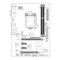
Internal
Connectors
1 x 24-pin ATX main power connector
1 x 8-pin ATX 12V power connector
1 x CPU fan header
3 x system fan headers
1 x RGB LED strip header
6 x SATA 6Gb/s connectors
2 x M.2 Socket 3 connectors
1 x front panel header
1 x front panel audio header
1 x S/PDIF Out header
1 x USB 3.1 Gen 1 header
2 x USB 2.0/1.1 headers
1 x Thunderbolt
™
add-in card connector
1 x Trusted Platform Module (TPM) header (2x6 pin, for the GC-TPM2.0_S
module only)
1 x parallel port header
1 x serial port header
1 x Clear CMOS jumper
Back Panel
Connectors
1 x PS/2 keyboard/mouse port
1 x D-Sub port
1 x DVI-D port
1 x HDMI port
1 x USB 3.1 Gen 2 Type-A port (red)
3 x USB 3.1 Gen 1 ports
2 x USB 2.0/1.1 ports
1 x RJ-45 port
6 x audio jacks
I/O Controller iTE
®
I/O Controller Chip
- 7 -