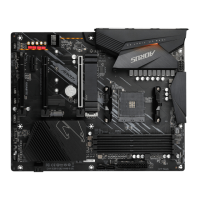
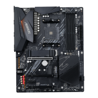
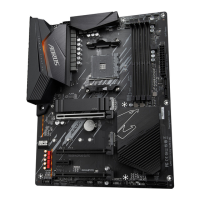
14) M2A_CPU/M2B_SB (M.2 Socket 3 Connectors)
TheM.2connectorssupportM.2SATASSDsorM.2PCIeSSDsandsupportRAIDconguration.Please
notethatanM.2PCIeSSDcannotbeusedtocreateaRAIDseteitherwithanM.2SATASSDoraSATA
harddrive.RefertoChapter3,"ConguringaRAIDSet,"forinstructionsonconguringaRAIDarray.
Follow the steps below to correctly install an M.2 SSD in the M.2 connector.
Step 1:
Locate the M.2 connector where you will install the M.2 SSD, use a screwdriver to unfasten the screw on
the heatsink and then remove the heatsink.
Step 2:
Locate the proper mounting hole based on the length of your M.2 SSD drive. If needed, move the standoff
to the desired mounting hole. Insert the M.2 SSD into the M.2 connector at an angle.
Step 3:
PresstheM.2SSDdownandthensecureitwiththescrew.Replacetheheatsinkandsecureittotheoriginal
hole.Makesuretoremovetheprotectivelmfromthebottomoftheheatsinkbeforereplacingtheheatsink.
F_USB30
F_U
B_
F_ F_
_
B
BS_
B
SB_
B
_S
S_
_
B
_U
_
B
S
123
123
123
123
1
1
1
1
BSS
S
_S
SSU
1 2 3
S3
BSSS
U
__ 3
F_USB3F
S _
S _
S _
SF
B_
B_
F
_0
S
S
_0F
_F
_
_
__B
U
S _S
_
SF_
B
USB0_B
B_
B_
F_USB3
F_USB303
_
_3U
S_
80110 60 42
M2A_CPU
F_USB30
F_U
B_
F_ F_
_
B
BS_
B
SB_
B
_S
S_
_
B
_U
_
B
S
123
123
123
123
1
1
1
1
BSS
S
_S
SSU
1 2 3
S3
BSSS
U
__ 3
F_USB3F
S _
S _
S _
SF
B_
B_
F
_0
S
S
_0F
_F
_
_
__B
U
S _S
_
SF_
B
USB0_B
B_
B_
F_USB3
F_USB303
_
_3U
S_
80110 60 42
M2B_SB
(Note)
(Note) The PCIEX4 slot shares bandwidth with the M2B_SB connector. The PCIEX4 slot becomes unavailable
when a device is installed in the M2B_SB connector.
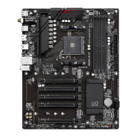
12) SATA3 3 (SATA 6Gb/s Connector)
The SATA connector supports SATA DOM device. The SATA connectors conform to SATA 6Gb/s standard
and are compatible with SATA 3Gb/s and SATA 1.5Gb/s standard. Each SATA connector supports a single
SATAdevice.TheSATAconnectorssupportRAID0,RAID1,andRAID10.RefertoChapter3,"Conguring
aRAIDSet,"forinstructionsonconguringaRAIDarray.
Pin No. Denition Pin No. Denition
1 GND 6 RXP
2 TXP 7 GND
3 TXN 8 +5V
4 GND 9 GND
5 RXN
SATA3
7
8
1
9
3
13) SATA_DOM0 (SATA DOM Power Header)
The header can provide power to SATA DOM devices.
Pin No. Denition
1 +5V
2 GND
3 NC
1
3
- 20 -
 Loading...