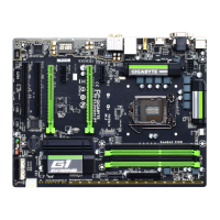
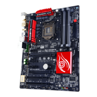
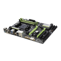
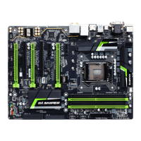
- 27 - Hardware Installation
3/4/5) CPU_FAN/SYS_FAN/FAN1/FAN2/FAN3 (Fan Headers)
All fan headers on this motherboard are 4-pin and support fan speed control function. Most fan headers
possess a foolproof insertion design. When connecting a fan cable, be sure to connect it in the correct
orientation (the black connector wire is the ground wire). The speed control function requires the use of
a fan with fan speed control design. For optimum heat dissipation, it is recommended that a system fan
be installed inside the chassis.
• Be sure to connect fan cables to the fan headers to prevent your CPU and system from over-
heating. Overheating may result in damage to the CPU or the system may hang.
• These fan headersare not congurationjumper blocks. Do not place a jumper cap on the
headers.
CPU_FAN
1
6) HP_PWR (Heatsink LED Power Connector)
The power connector provides power to the LEDs on the North Bridge heatsink.
1
Pin No. Denition
1 VCC
2 GND
CPU_FAN:
SYS_FAN/FAN1/FAN2/FAN3:
Pin No. Denition
1 GND
2 +12V
3 Sense
4 Speed Control
Pin No. Denition
1 GND
2 +12V / Speed Control
3 Sense
4 Reserve
 Loading...