- 33 - Hardware Installation
13) F_AUDIO (Front Panel Audio Header)
The front panel audio header supports Intel High Denition audio (HD). You may connect your chassis
front panel audio module to this header. Make sure the wire assignments of the module connector match
the pin assignments of the motherboard header. Incorrect connection between the module connector and
the motherboard header will make the device unable to work or even damage it.
Some chassis provide a front panel audio module that has separated connectors on each wire
instead of a single plug. For information about connecting the front panel audio module that has
different wire assignments, please contact the chassis manufacturer.
Pin No. Denition
1 MIC2_L
2 GND
3 MIC2_R
4 -ACZ_DET
5 LINE2_R
6 GND
7 FAUDIO_JD
8 No Pin
9 LINE2_L
10 GND
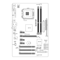
F_USB30
F_AUDIO(H)
DB_PORT
F_PANEL(NH) F_PANEL
(H61M-D2)
ACPI_CPT
(GA-IVB)
BIOS_PH
(GA-IVB)
SMB_CPT
(GA-IVB)
CLR_CMOS
CI
DIS_ME
GP15_CPT
(GA-IVB)
XDP_CPU
XDP_PCH
(GA-IVB)
TPM
w/housing
Voltage measurement module(X58A-OC)
PCIe power connector (SATA)(X58A-OC)
DIP
1 2 3
DIP
1 2 3
DIP
1 2 3
DIP
123
1
1
1
1
BIOS Switcher (X58A-OC)
PWM Switch (X58A-OC)
M_SATA
PWM Switch (SW1)(X79-UD7)
DIP
1 2 3 4 5
Voltage measurement points(G1.Sniper 3)
BIOS Switcher (SW4)
9
1
10 2
14) CLR_CMOS (Clear CMOS Jumper)
Use this jumper to clear the CMOS values (e.g. date information and BIOS congurations) and reset the
CMOS values to factory defaults. To clear the CMOS values, use a metal object like a screwdriver to touch
the two pins for a few seconds.
Always turn off your computer and unplug the power cord from the power outlet before clearing •
the CMOS values.
After system restart, go to BIOS Setup to load factory defaults (select Load Optimized •
Defaults) or manually congure the BIOS settings (refer to Chapter 2, "BIOS Setup," for BIOS
congurations).
Open: Normal
Short: Clear CMOS Values

 Loading...