Do you have a question about the Gigabyte GA-586HX and is the answer not in the manual?
Provides a welcome and overview of the motherboard manual.
Lists the main specifications and capabilities of the GA-586HX motherboard.
Presents benchmark test results for the motherboard's performance.
Displays the architectural block diagram of the motherboard.
Explains the PCI bus standard, its benefits and design.
Lists general features and specifications related to the PCI bus.
Details the hardware components and specifications of the motherboard.
Lists supported operating systems and included software utilities.
Specifies the operating environment conditions for the motherboard.
Instructions on how to unpack the motherboard and check for damage.
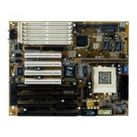
Identifies key components and connectors on the motherboard.
Provides a guide to jumpers and connectors on the motherboard.
Step-by-step guide for installing DRAM modules.
Instructions for installing Sync. SRAM modules.
Guide for installing the CPU and setting up related jumpers.
Information about the onboard RTC and CMOS SRAM.
How to connect the system speaker.
Instructions for connecting power LED and key lock.
How to connect the turbo switch for system speed control.
How to connect the turbo LED indicator.
How to connect the hardware reset switch.
Instructions for setting up power saving features.
Guidance on installing peripheral devices like graphics cards.
Describes special keyboard functions for system control.
Steps to access the BIOS setup utility.
Explains the keys used for navigation within the BIOS setup.
How to access help information within the BIOS setup.
Overview of the BIOS setup main menu options.
Details on configuring standard CMOS settings.
Options for configuring advanced BIOS features.
Settings related to the motherboard chipset features.
Configuration options for power saving features.
Settings for Plug and Play and PCI device configuration.
How to load default BIOS settings.
How to load default setup settings.
Configuration for onboard peripherals like IDE, FDD, Serial/Parallel ports.
How to set up system and setup passwords.
How to automatically detect IDE hard disk parameters.
Procedure for performing a low-level format of the hard disk.
How to save changes and exit the BIOS setup.
How to exit BIOS setup without saving changes.
Pinout details for I/O bus connectors.
Pinout information for ISA slots.
Pinout information for PCI bus slots.
Maps of I/O ports and memory addresses.
Maps of timer and DMA channels.
Lists Interrupt (IRQ) assignments.
Map of RTC and CMOS RAM registers.
Describes POST beep codes and their meanings.
Lists common POST error messages and their causes.
Detailed list of POST codes and their descriptions.
Table of default hard drive parameters for BIOS setup.
Section for customer information.
Fields for mainboard model and revision.
Section to record system hardware details.
Space to note AUTOEXEC.BAT and CONFIG.SYS files.
Area to describe the reported problem.
| Form Factor | AT |
|---|---|
| Socket Type | Socket 7 |
| Chipset | Intel 430HX |
| Memory Slots | 4 |
| Maximum Memory | 512 MB |
| IDE Ports | 2 |
| PCI Slots | 4 |
| USB Ports | 2 |
| ISA Slots | 3 |
| BIOS | Award |
| CPU Type | Intel Pentium, AMD K5, AMD K6, Cyrix 6x86 |
| Memory Type | EDO |