GA-965G-DS3 Motherboard - 20 -
English
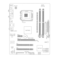
3/4/5) CPU_FAN / SYS_FAN / PWR_FAN (Cooler Fan Power Connector)
The cooler fan power connector supplies a +12V power voltage via a 3-pin/4-pin (CPU_FAN/
SYS_FAN) power connector and possesses a foolproof connection design.
Most coolers are designed with color-coded power connector wires. A red power connector wire
indicates a positive connection and requires a +12V power voltage. The black connector wire is
the ground wire (GND).
Remember to connect the CPU/system/power fan cable to the CPU_FAN/SYS_FAN/PWR_FAN
connector to prevent CPU damage or system hanging caused by overheating.
SYS_FAN
1
1
CPU_FAN
1
PWR_FAN
Pin No. Definition
1 GND
2 +12V / Speed Control
3 Sense
4 Speed Control
CPU_FAN / SYS_FAN :
Pin No. Definition
1 GND
2 +12V
3 Sense
PWR_FAN :
6) NB_FAN (Chip Fan Connector)
If you installed wrong direction, the chip fan will not work. Sometimes will damage the chip fan.
(Usually black cable is GND)
1
Pin No. Definition
1 GND
2 +12V
3NC
NB_FAN :
 Loading...