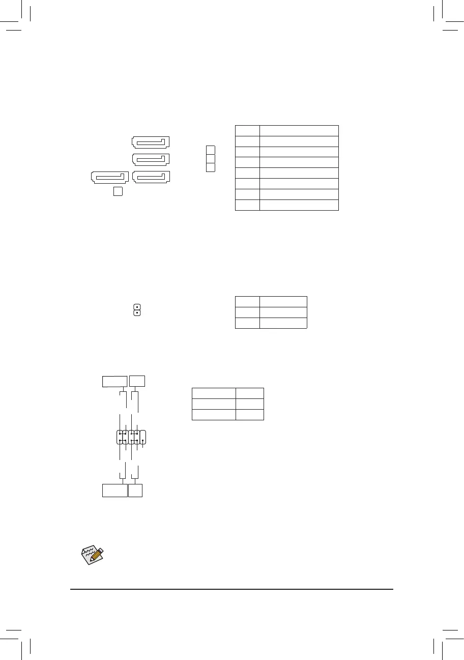
5) SATA3 0/1/2/3 (SATA 6Gb/s Connectors)
The SATA connectors conform to SATA 6Gb/s standard and are compatible with SATA 3Gb/s and
SATA 1.5Gb/s standard. Each SATA connector supports a single SATA device. The SATA connectors
supportRAID0,RAID1,andRAID10.RefertoChapter3,"ConguringaRAIDSet,"forinstructions
onconguringaRAIDarray.
Pin No. Denition
1 GND
2 TXP
3 TXN
4 GND
5 RXN
6 RXP
7 GND
71
SATA3
0
1
7
71
SATA3
3
2
1
6) SPDIF_O (S/PDIF Out Header)
This header supports digital S/PDIF Out and connects a S/PDIF digital audio cable (provided by expansion
cards) for digital audio output from your motherboard to certain expansion cards like graphics cards and
sound cards. For example, some graphics cards may require you to use a S/PDIF digital audio cable for
digital audio output from your motherboard to your graphics card if you wish to connect an HDMI display
to the graphics card and have digital audio output from the HDMI display at the same time. For information
about connecting the S/PDIF digital audio cable, carefully read the manual for your expansion card.
Pin No. Denition
1 SPDIFO
2 GND
1
7) F_PANEL (Front Panel Header)
Connect the power switch, reset switch and system status indicator on the chassis to this header according
to the pin assignments below. Note the positive and negative pins before connecting the cables.
System Status LED
S0 On
S3/S4/S5 Off
• PLED (Power LED):
Connects to the power status indicator
on the chassis front panel. The LED is on
when the system is operating. The LED is
off when the system is in S3/S4 sleep state
or powered off (S5).
• PW (Power Switch):
Connects to the power switch on the chassis front panel. You may
congurethewaytoturnoffyoursystemusingthepowerswitch(refer
to Chapter 2, "BIOS Setup," "Power," for more information).
• HD (Hard Drive Activity LED):
Connects to the hard drive activity LED on the chassis front panel. The
LED is on when the hard drive is reading or writing data.
The front panel design may differ by chassis. A front panel module mainly consists of power
switch, reset switch, power LED, hard drive activity LED and etc. When connecting your chassis
front panel module to this header, make sure the wire assignments and the pin assignments are
matched correctly.
Hard Drive
Activity LED
Reset
Switch
1
2
9
10
NC
PLED-
PW-
PLED+
PW+
HD-
RES+
HD+
RES-
Power LED
Power
Switch
• RES (ResetSwitch):
Connects to the reset switch on the chassis front panel. Press the reset switch to restart the computer if the
computerfreezesandfailstoperformanormalrestart.
• NC: No connection.
- 14 -
 Loading...