Hardware Installation- 25 -
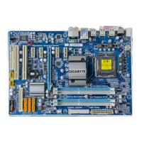
7) IDE1 (IDE Connector)
The IDE connector supports up to two IDE devices such as hard drives and optical drives. Before
attaching the IDE cable, locate the foolproof groove on the connector. If you wish to connect two IDE
devices, remember to set the jumpers and the cabling according to the role of the IDE devices (for
example, master or slave). (For information about configuring master/slave settings for the IDE
devices, read the instructions from the device manufacturers.)
40
39
2
1
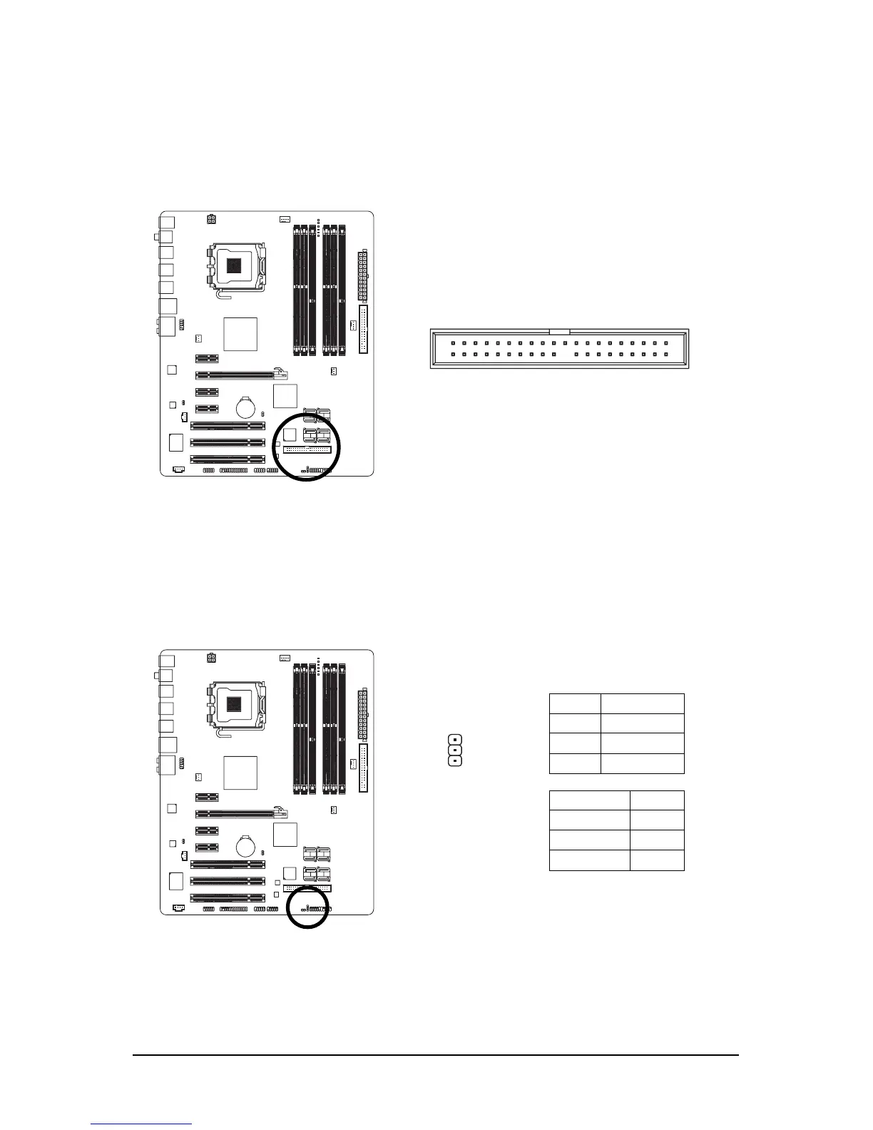
8) PWR_LED (System Power LED Header)
This header can be used to connect a system power LED on the chassis to indicate system power
status. The LED is on when the system is operating. The LED keeps blinking when the system is
in S1 sleep state. The LED is off when the system is in S3/S4 sleep state or powered off (S5).
Pin No. Definition
1 MPD+
2 MPD-
3 MPD-
System Status LED
S0 On
S1 Blinking
S3/S4/S5 Off
1
 Loading...