131
2412
ATX
ATX:
PinNo. Denition PinNo. Denition
1 3.3V 13 3.3V
2 3.3V 14 -12V
3 GND 15 GND
4 +5V 16 PS_ON(softOn/Off)
5 GND 17 GND
6 +5V 18 GND
7 GND 19 GND
8 Power Good 20 NC
9 5VSB(standby+5V) 21 +5V
10 +12V 22 +5V
11 +12V(Only for 2x12-pin
ATX)
23 +5V(Onlyfor2x12-pinATX)
12 3.3V (Only for 2x12-pin
ATX)
24 GND(Onlyfor2x12-pinATX)
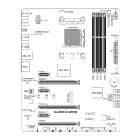
3/4) CPU_FAN/SYS_FAN (Fan Headers)
All fan headers on this motherboard are 4-pin. Most fan headers possess a foolproof insertion design.
Whenconnectingafancable,besuretoconnectitinthecorrectorientation(theblackconnectorwireis
thegroundwire).Thespeedcontrolfunctionrequirestheuseofafanwithfanspeedcontroldesign.For
optimum heat dissipation, it is recommended that a system fan be installed inside the chassis.
• Be sure to connect fan cables to the fan headers to prevent your CPU and system from
overheating. Overheating may result in damage to the CPU or the system may hang.
• Thesefanheadersarenotcongurationjumperblocks.Donotplaceajumpercapontheheaders.
CPU_FAN/SYS_FAN
1
PinNo. Denition
1 GND
2 VoltageSpeedControl
3 Sense
4 PWMSpeedControl
1/2) ATX_12V/ATX (2x2 12V Power Connector and 2x12 Main Power Connector)
Withtheuseofthepowerconnector,thepowersupplycansupplyenoughstablepowertoallthecomponents
onthemotherboard.Beforeconnectingthepowerconnector,rstmakesurethepowersupplyisturned
off and all devices are properly installed. The power connector possesses a foolproof design. Connect the
power supply cable to the power connector in the correct orientation.
The12VpowerconnectormainlysuppliespowertotheCPU.Ifthe12Vpowerconnectorisnotconnected,
the computer will not start.
To meet expansion requirements, it is recommended that a power supply that can withstand high power consumption
beused(500Worgreater).Ifapowersupplyisusedthatdoesnotprovidetherequiredpower,theresultcan
lead to an unstable or unbootable system.
ATX_12V:
PinNo. Denition
1 GND
2 GND
3 +12V
4 +12V
ATX_12V
2
1
4
3
- 13 -
 Loading...