SATA3 0 SATA3 1 SATA3 2 SATA3 3 SATA3 4 SATA3 5
M.2 SATA SSD
r a a a a a
M.2 PCIe x4 SSD
a a a a a a
M.2 PCIe x2 SSD
a a a a a a
NoM.2SSDInstalled
a a a a a a
a: Available, r:Notavailable.
Connector
Type of
M.2 SSD
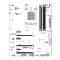
Installation Notices for the M.2 and SATA Connectors:
Due to the limited number of lanes provided by the Chipset, the availability of the SATA connectors may be
affectedbythetypeofdeviceinstalledintheM2A_32Gconnector.TheM2A_32Gconnectorsharesbandwidth
withtheSATA30connector.Refertothefollowingtablefordetails.
The front panel design may differ by chassis. A front panel module mainly consists of power switch, reset
switch,powerLED,harddriveactivityLED,speakerandetc.Whenconnectingyourchassisfrontpanel
module to this header, make sure the wire assignments and the pin assignments are matched correctly.
8) F_PANEL (Front Panel Header)
Connect the power switch, reset switch, speaker, chassis intrusion switch/sensor and system status indicator
onthechassistothisheaderaccordingtothepinassignmentsbelow.Notethepositiveandnegativepins
before connecting the cables.
System Status LED
S0 On
S3/S4/S5 Off
• PW (PowerSwitch):
Connects to the power switch on the chassis front panel. You may
congurethewaytoturnoffyoursystemusingthepowerswitch(refer
toChapter2,"BIOSSetup,""Power,"formoreinformation).
• SPEAK (Speaker):
Connects to the speaker on the chassis front panel. The system reports
system startup status by issuing a beep code. One single short beep
will be heard if no problem is detected at system startup.
• PLED/PWR_LED (PowerLED):
Connects to the power status indicator
on the chassis front panel. The LED is on
when the system is operating. The LED is
off when the system is in S3/S4 sleep state
orpoweredoff(S5).
• HD (HardDriveActivityLED):
Connects to the hard drive activity LED on the chassis front panel. The LED is on when the hard drive is
reading or writing data.
• RES (ResetSwitch):
Connects to the reset switch on the chassis front panel. Press the reset switch to restart the computer if the
computer freezes and fails to perform a normal restart.
• CI (ChassisIntrusionHeader):
Connects to the chassis intrusion switch/sensor on the chassis that can detect if the chassis cover has been
removed. This function requires a chassis with a chassis intrusion switch/sensor.
• NC: Noconnection.
SPEAK+
SPEAK-
Speaker
NC
NC
Hard Drive
Activity LED
1
2
19
20
CI-
CI+
PLED-
PW-
PLED+
PW+
HD-
RES+
HD+
RES-
Reset
Switch
Chassis
Intrusion Header
Power Switch
F_USB30
F_U
B_
F_ F_
_
B
BS_
B
SB_
B
_S
S_
_
B
_U
_
B
S
123
123
123
123
1
1
1
1
BSS
S
_S
SSU
1 2 3
S3
BSSS
U
__ 3
F_USB3F
S _
S _
S _
SF
B_
B_
F
_0
S
S
_0F
_F
_
_
__B
U
S _S
_
USB0_B
B_
F_USB3
Power LED
Power LED
PWR_LED-
PWR_LED+
PWR_LED-
- 15 -
 Loading...