4 2
3 1
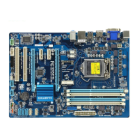
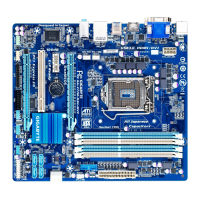
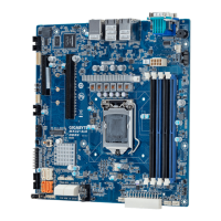
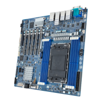
1) ATX_12V (2x4 12V Power Connector)
With the use of the power connector, the power supply can supply enough stable power to all the
componentsonthemotherboard.Before connectingthepowerconnector, rst makesurethepower
supply is turned off and all devices are properly installed. The power connector possesses a foolproof
design. Connect the power supply cable to the power connector in the correct orientation. The 12V
power connector mainly supplies power to the CPU. If the 12V power connector is not connected, the
computer will not start.
To meet expansion requirements, it is recommended that a power supply that can withstand high
power consumption be used (500W or greater). If a power supply is used that does not provide the
required power, the result can lead to an unstable or unbootable system.
PinNo. Denition
1 GND
2 GND
3 +12V
4 +12V
PinNo. Denition
1 GND
2 GND
3 VIN_IN
4 VIN_IN
5 GND
6 GND
7 GND
8 GND
9 GND
ATX_12V
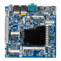
2) DC_IN (SC In Power Connector)
GND (Pin 1 & 2)
VIN (Pin 3 & 4)
 Loading...