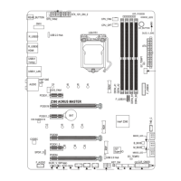
15) F_AUDIO (Front Panel Audio Header)
The front panel audio header supports High Denition audio (HD). You may connect your chassis front
panel audio module to this header. Make sure the wire assignments of the module connector match the
pin assignments of the motherboard header. Incorrect connection between the module connector and the
motherboard header will make the device unable to work or even damage it.
Some chassis provide a front panel audio module that has separated connectors on each wire instead
of a single plug. For information about connecting the front panel audio module that has different wire
assignments, please contact the chassis manufacturer.
F_USB30
F_U
B_
F_ F_
_
B
BS_
B
SB_
B
_S
S_
_
B
_U
_
B
S
123
123
123
123
1
1
1
1
BSS
S
_S
SSU
1 2 3 4 5
S3
BSSS
U
__ 3
F_USB3F
S _
S _
S _
SF
B_
B_
F
_0
S
S
_0F
_F
_
_
__B
U
S _S
_
SF_
USB0_B
B_
F_USB3
F_USB303
_
_3U
S_
9
1
10 2
Pin No. Denition Pin No. Denition
1 MIC2_L 6 Sense
2 GND 7 FAUDIO_JD
3 MIC2_R 8 No Pin
4 NC 9 LINE2_L
5 LINE2_R 10 Sense
16) SPDIF_O (S/PDIF Out Header)
This header supports digital S/PDIF Out and connects a S/PDIF digital audio cable (provided by expansion
cards) for digital audio output from your motherboard to certain expansion cards like graphics cards and
sound cards. For example, some graphics cards may require you to use a S/PDIF digital audio cable for
digital audio output from your motherboard to your graphics card if you wish to connect an HDMI display
to the graphics card and have digital audio output from the HDMI display at the same time. For information
about connecting the S/PDIF digital audio cable, carefully read the manual for your expansion card.
Pin No. Denition
1 5VDUAL
2 No Pin
3 SPDIFO
4 GND
1
F_USB30
F_U
B_
F_ F_
_
B
BS_
B
SB_
B
_S
S_
_
B
_U
_
B
S
123
123
123
123
1
1
1
1
BSS
S
_S
SSU
1 2 3 4 5
S3
BSSS
U
__ 3
F_USB3F
S _
S _
S _
SF
B_
B_
F
_0
S
S
_0F
_F
_
_
__B
U
S _S
_
SF_
USB0_B
B_
F_USB3
F_USB303
_
_3U
S_
- 22 -
17) CPU/DRAM/VGA/BOOT (Status LEDs)
The status LEDs show whether the CPU, memory, graphics card, and operating system are working
properly after system power-on. If the CPU/DRAM/VGA LED is on, that means the corresponding device
is not working normally; if the BOOT LED is on, that means you haven't entered the operating system yet.
CPU: CPU status LED
DRAM: Memory status LED
VGA: Graphics card status LED
BOOT: Operating system status LED
F_USB30
F_U
B_
F_ F_
_
B
BS_
B
SB_
B
_S
S_
_
B
_U
_
B
S
123
123
123
123
1
1
1
1
BSS
S
_S
SSU
1 2 3 4 5
S3
BSSS
U
__ 3
F_USB3F
S _
S _
S _
SF
B_
B_
F
_0
S
S
_0F
_F
_
_
__B
U
S _S
_
SF_
USB0_B
B_
F_USB3
F_USB303
_
_3U
S_
CPU DRAM
VGA BOOT
 Loading...