- 27 -
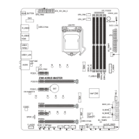
19) F_AUDIO (Front Panel Audio Header)
The front panel audio header supports High Denition audio (HD). You may connect your chassis front
panel audio module to this header. Make sure the wire assignments of the module connector match the
pin assignments of the motherboard header. Incorrect connection between the module connector and the
motherboard header will make the device unable to work or even damage it.
Pin No. Denition Pin No. Denition
1 MIC L 6 MIC Detection
2 GND 7 SENSE_SEND
3 MIC R 8 No Pin
4 NC 9 Head Phone L
5 Head Phone R 10 Head Phone Detection
Some chassis provide a front panel audio module that has separated connectors on each wire
instead of a single plug. For information about connecting the front panel audio module that has
different wire assignments, please contact the chassis manufacturer.
F_USB30
F_U
B_
F_ F_
_
B
BS_
B
SB_
B
_S
S_
_
B
_U
_
B
S
123
123
123
123
1
1
1
1
BSS
S
_S
SSU
1 2 3
S3
BSSS
U
__ 3
F_USB3F
S _
S _
S _
SF
B_
B_
F
_0
S
S
_0F
_F
_
_
__B
U
S _S
_
SF_
B
USB0_B
B_
B_
F_USB3
F_USB303
_
_3U
S_
_S
SS_F
_
_
F
_SB
9 1
10 2
Suggested F_AUDIO header routing:
Step 1:
Use a screwdriver to unfasten the screw on the
heatsink and then remove the heatsink.
Default location of
the F_AUDIO header
Heatsink
GC-Z790I
BTB PLUG
Step 2:
Use a screwdriver to remove the screw from GC-Z790I BTB
PLUG. Lift the GC-Z790I BTB PLUG upwards and remove it.
Step 3:
Move the F_AUDIO header out of its default location and route
it via the BTB connector to the bottom edge of the motherboard
as shown on the left.
Step 4:
Insert GC-Z790I BTB PLUG vertically into the BTB connectors
and secure it with the screw. Then screw the heatsink back on.
GC-Z790I
BTB PLUG
& Please visit GIGABYTE's website for details on using the front panel audio header.
https://www.gigabyte.com/WebPage/955/Z790I-AORUS-ULTRA-audio.html
 Loading...