The 98GCK-49 is a comprehensive kit designed for controlling a single DC awning with integrated LED lighting, featuring both a standard rocker switch and a hard-wired motion sensor. This system is available in either black or white, indicated by the "B" or "W" suffix in the model numbers (98GC781 for the rocker switch and 98GC780 for the motion sensor). The core components, the motion sensor and the rocker switch, communicate using the RS485 protocol, ensuring reliable operation.
Function Description:
The primary function of the 98GCK-49 kit is to provide versatile control over an RV awning and its associated LED lights. The rocker switch allows for manual extension and retraction of the awning, as well as independent control of the LED lighting. The wired motion sensor adds an automated layer of control, designed to retract the awning under certain conditions, primarily related to wind sensitivity.
A key safety feature integrated into the system is the Ignition Retract-Lock function. This mechanism automatically retracts the awning if the vehicle's engine is turned on, preventing accidental deployment or damage during travel. The wiring diagram (Fig. 6) illustrates how to connect this function.
Important Technical Specifications:
- Operating Voltage: The system operates within a voltage range of 11 VDC to 14 VDC, making it suitable for standard RV electrical systems.
- Current: It can handle a maximum current of up to 10A. This specification is crucial for ensuring the appropriate fuse protection, as indicated by the 10Amp fuse protection in the wiring diagram (Fig. 6).
- LED Light Control: The system includes dedicated controls for the LED lighting integrated with the awning.
- Communication Protocol: RS485 is used for communication between the motion sensor and the rocker switch, ensuring robust data exchange.
- Maximum Run Time: The awning motor has a maximum run time of 2 minutes, likely a safety feature to prevent motor burnout or continuous operation if an obstruction is encountered.
- Operating Temperature: The device is designed to operate effectively in temperatures ranging from 0°C to 50°C.
Usage Features:
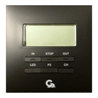
The rocker switch (98GC781) is the primary interface for manual control. It features several clearly labeled buttons:
- IN Button: Retracts the awning.
- STOP Button: Halts the awning's movement at any point during extension or retraction.
- OUT Button: Extends the awning.
- ON Button: Turns on the LED light.
- OFF Button: Turns off the LED light.
- CLOSE/OFF Button: This is a combined command that closes the awning and simultaneously turns off the LED light.
Wind Sensitivity Adjustment:
The system offers a sophisticated wind sensitivity adjustment feature with 10 distinct levels, allowing users to customize how the motion sensor responds to wind. This adjustment is performed directly on the rocker switch controller:
- Remove the cover from the rocker switch.
- Press and hold the "set button" (located as shown in Fig. 2) for 10 seconds until a beep is heard from the controller.
- Use the "UP" or "Down" buttons (likely referring to the IN/OUT buttons used for awning control, or dedicated sensitivity buttons if present under the cover) to increase or decrease the sensitivity level.
- The "Setting LED" will illuminate with each press, indicating the current level.
- Once the desired sensitivity level is selected, press and hold the "set button" again until three beeps are heard, confirming the setting has been saved.
Reverse Motor Direction:
In cases where the awning motor's direction is reversed (e.g., "IN" extends instead of retracts), the system allows for easy correction without rewiring:
- Simultaneously press and hold both the "IN" and "OUT" buttons on the wall switch.
- Continue holding for at least 6 seconds until a beep is heard, indicating the motor direction has been reversed.
Motion Sensor (98GC780):
The wired motion sensor is designed to be attached to the awning's lead rail using a mounting tab and screw (Fig. 3, Fig. 4, Fig. 5). It communicates directly with the DC motor controller (98GC781) via RS485 protocol. While the manual doesn't explicitly detail its operational triggers beyond "wind sensitivity," its primary role is to provide automated retraction based on detected motion or environmental conditions, acting as a safeguard for the awning.
Installation and Mounting:
- Rocker Switch: The rocker switch requires a wall opening of 2.6 inches x 2.6 inches with a depth of 1.25 inches for proper installation (Fig. 2).
- Motion Sensor: The motion sensor is attached to the lead rail using its mounting tab and screw.
Maintenance Features:
The manual emphasizes several crucial points regarding the operation and maintenance of the awning to ensure longevity and prevent damage:
- Weather Conditions: Awnings can be operated in light wind and rain. However, they must be closed during periods of heavy rain or high winds and should never be left open and unattended under such conditions. Damage resulting from wind and rain is explicitly not covered by warranty.
- Vehicle Movement: All awnings must be closed before moving the vehicle for any reason. A visual check to confirm full closure is recommended as an extra safety precaution. Damage due to non-compliance with these instructions is not covered by warranty.
- Obstructions: Before deploying the awning, users must ensure the area is clear of any obstructions such as trees, walls, pillars, posts, or other vehicles. Damage caused by collisions with any of these or similar objects is not covered by warranty.
Wiring Diagram (Fig. 6 & Fig. 7):
The wiring diagrams provide detailed connections for the system components:
- Circuit Panel: Connects to a 12 Volts DC power source with 10Amp fuse protection.
- User Rocker Switches: Contains terminals for V+ (Power +12V DC), G (Ground), M+ (DC Motor Brown), M- (DC Motor Blue), LED G (LED/Motion Sensor Ground), V12 (Motion Sensor 12 V DC), B (Signal +), and G (Signal -).
- Ignition LockOut: A dedicated connection for the ignition retract-lock function.
- Arm Wire: A 5-conductor wire connects the rocker switch to the motion sensor, LED lights, and DC motor.
- Awning: Represents the awning mechanism.
- Motion Sensor: Connected to the rocker switch for communication and power.
- LED Lights: Integrated with the awning and controlled by the rocker switch.
- DC Motor: Powers the awning's extension and retraction.
The detailed terminal descriptions in Fig. 7 clarify the function of each connection point on the rocker switch, facilitating correct wiring.
For any queries or assistance, Girard Systems provides a toll-free support line at 800-382-8442, available between 7:30 am and 3:30 pm P.S.T.