2
User Guide
Ultrasonic Humidifier
CONTENTS
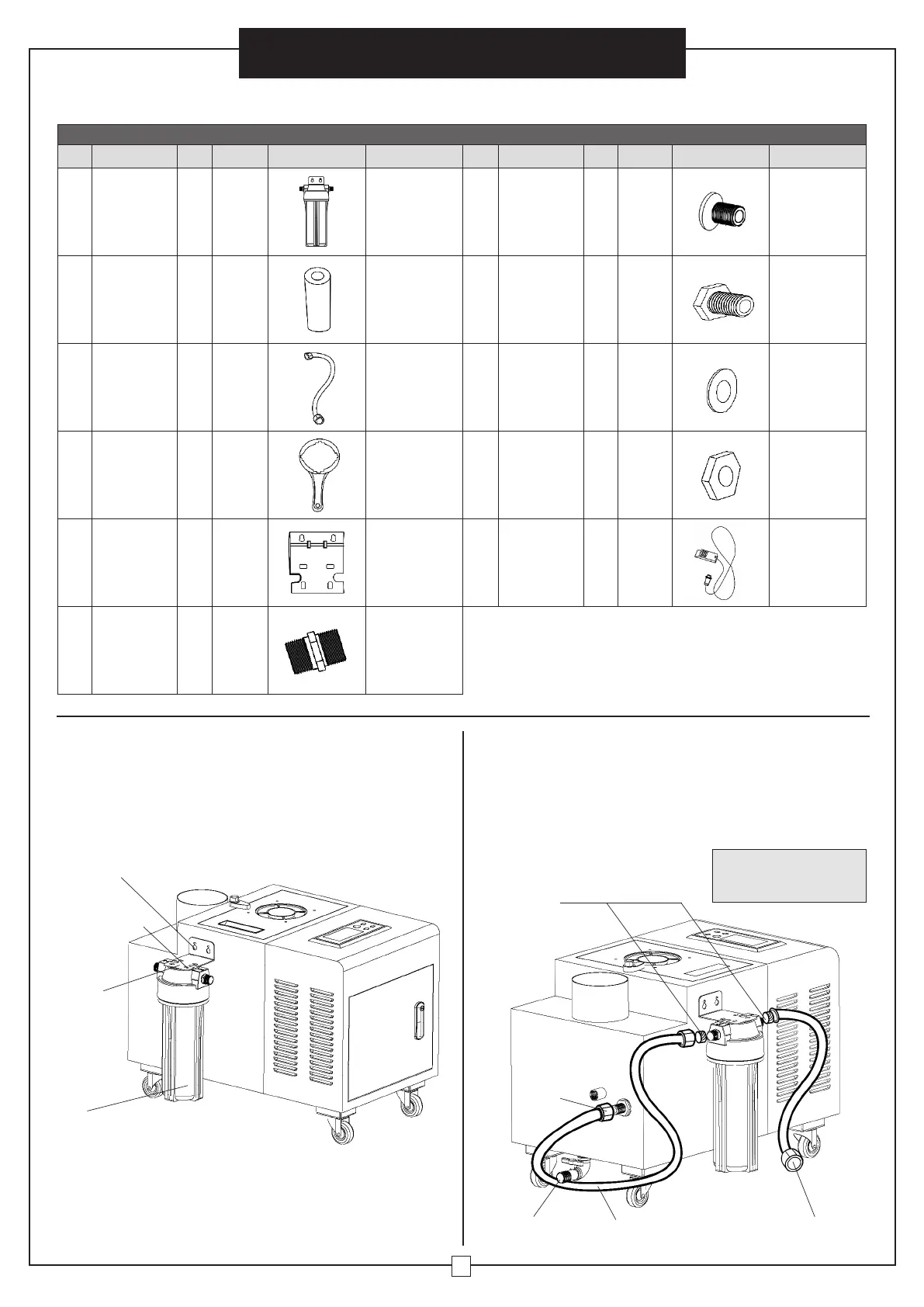
Ref. Description Qty. Spec. Image Note Ref. Description Qty. Spec. Image Note
H1
Filter 1 --- See Figure 3
H7
Screw 4 ST4* 16 See Figure 3
H2 Filter Element 2 PP
Place filter
element into
filter. Second
one is a
replacement
H8 Screw 2 M6* 16 See Figure 3
H3
Connecting
Hose
2
19
11
/16"
See Figure 4 H9 Flat Washer 8 Ø12* 6 See Figure 3
H4 Spanner 1 ---
Used to loosen
cover of filter
container to
clean filter.
See Figure 10
H10 Nut 2 M6 See Figure 3
H5
Mounting
Bracket
1 ---
Fixed on the
side panel.
See Figure 3
H11
Humidity
Sensor
1 32' See Figure 2
H6
Hose
Connector
2
Outer
Dia.
DN15
(1/4")
See Figure 4
ASSEMBLY
Filter Installation
Install water filter using the mounting bracket as illustrated
in Figure 3. The filter enables the humidifier's water
system to run smoothly, and prevents water impurities
from flowing into the unit blocking the solenoid valve
and clogging the system.
Figure 3
Figure 4
1. Filter Bracket
• Attach bracket to the pre-drilled holes located on the
side of the unit.
• Using the four supplied screws, attach the filter
underneath the bracket (Figure 3).
2. Filter Connections
• Attach hose connectors onto ends of each hose.
• Hose A: Connect one end to the filter and the other end
to the water inlet port on the unit (Figure 4).
• Hose B: Connect one end to the filter and the other
end to the fresh water supply.
Bracket
(H8) Screw
(H10) Nut
(H7) Screw
(H9) Washer
Filter
Water
Inlet
Water Outlet
To Drain
Connector
Hose A
Connector Hose B
To Tap Water Supply
1/4" Hose
Connectors
Note: The height of the
connector hose A cannot
be higher than the outlet.
 Loading...