Supplied By www.heating spares.co Tel. 0161 620 6677
6
220562A
Diagram 3.2
3 U n p a c k i n g
Diagram 3.3
3.1 Unpacking
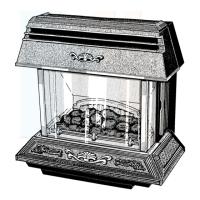
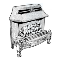
The fire front is delivered in two packs, one contains the
combustion chamber assembly, fuel pack(s) and loose
items pack. The other contains the fire front, fret, ash pit
cover and fire control knob extension.
Refer to diagram 3.1 to identify the parts.
Check contents of loose items pack against packed list.
3.2 Gas Supply to Fire Front
Check that the gas service cock is in the boiler only on
position, see diagram 3.2.
The inlet supply tube is packed with the loose items.
The supply tube may need to be cut at the larger end
dependent upon the position of the back boiler unit in the
opening.
Measure the distance “C”, see diagram 3.3, from the
front mark “P” on the air duct to the fire fixing wall face.
Use a straight edge across the opening.
Shorten the gas supply tube by distance “C” + 21mm at
the larger end.
The maximum distance for “C” will be 25mm (1inch).
Deburr the tube end inside and out.
GAS SERVICE
COCK UNION
BACK BOILER
ONLY 'ON'
BACK BOILER
AND FIRE 'ON'
'OFF'
GAS FIRE
SUPPLY TUBE
FIRE FIXING
WALL FACE
BACK
BOILER
AIR DUCT
(MAX. SHOWN) 'C'
'P'
'C'
'C'
2669
"C" = Distance from fire fixing wall face to
datums on back boiler air duct.
This represents the length of pipe
that requires cutting off.
3097
 Loading...