Supplied By www.heating spares.co Tel. 0161 620 6677
7
220562A
4 I n s t a l l a t i o n
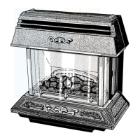
Diagram 4.1
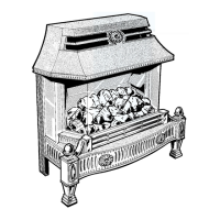
Diagram 4.2
4.1 Positioning the Combustion Chamber
Assembly
Note: Before fitting, again make sure the wall surface to
which the combustion chamber assembly is to be fitted is
vertical and flat. Any unevenness may cause the whole
assembly to become twisted or distorted when fixing to
the wall.
Place the combustion chamber assembly into the fire
opening and make sure that the flue spigot fits into the
boiler flue collector assembly and locates onto the back
boiler combustion chamber extension and burner
assembly, see diagram 4.1.
Push well back to the fire fixing wall face.
Mark the four combustion chamber assembly fixing
points (making sure that the area is sufficiently firm),
through the holes in the surround refer to diagram 4.2.
Pull the combustion chamber assembly forwards and
remove.
Drill the fire front fixing wall face, using a 10mm
masonry drill to a minimum depth of 40mm to accept the
reusable anchor nuts and screws provided.
Place the anchor nuts in the holes.
Note. If the fire front fixing wall face is not of a solid
construction to a minimum depth of 40mm, for example,
hollow brick or metal an alternative and rigid form of
fastening for the combustion chamber assembly must be
used and extra care taken.
Fit the combustion chamber assembly, making sure that
it is correctly positioned onto the back boiler unit, see
diagram 4.1, secure with the screws provided.
Important: If the electrical supply to the boiler comes
from the right, make sure that when fitting the
combustion chamber assembly the cable is routed and
clear, as shown in diagram 4.1.
2971
2970
B.B.U. COMBUSTION
CHAMBER EXTENSION
AND BURNER ASSEMBLY
FIRE FIXING
WALL FACE
FLUE COLLECTOR
ASSEMBLY
FLUE
SPIGOT
COMBUSTION CHAMBER ASSEMBLY
COMBUSTION CHAMBER ASSEMBLY
SECURING
SCREW
ANCHOR
NUT
=SECURING SCREW POSITION
 Loading...