14
Apollo Lasher
9. Raise the rear cable lifter by pushing up on the bottom of the lifter that
contacts the D shaft. The thumblatch doesn’t have to be activated to raise
the cable lifter.
10. Adjust the position of the vertical rollers so that they barely touch the
sides of the cable(s). This will have to be done as the bundle size changes.
See section 4.6 for more information on terminating lashing wire.
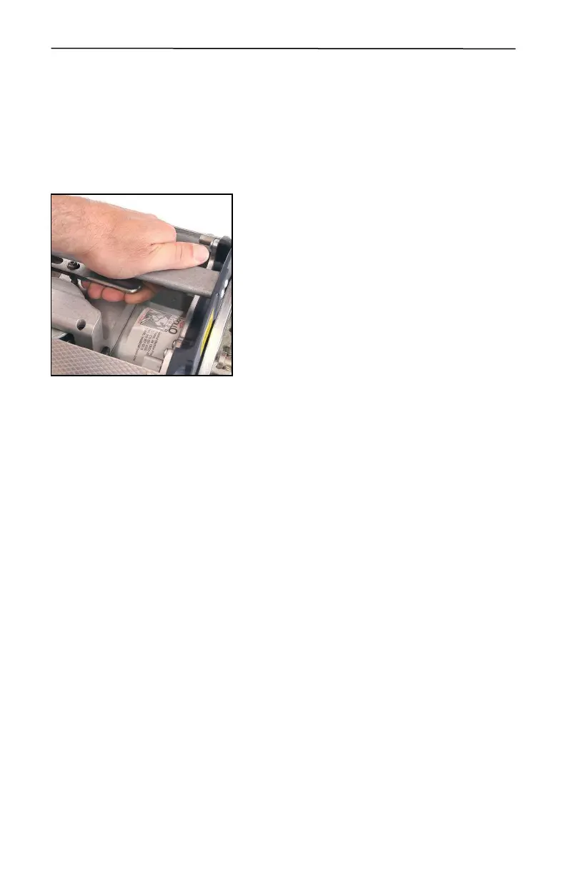
11. Now the final steps. Pull up on the
handle to de-clutch and disengage the drive
wheel to pull some lashing wire from the
lasher. Secure the lashing wire to the strand
by using a GMP D or E lashing wire clamp.
Attach the bridle assembly to the towing
eyes on the Apollo lasher and you are ready
to lash.
4.6 Lashing wire termination
4.6.1 General
A common cause of lashing wire failure is improper termination. The
following steps outline the suggested method for proper lashing wire
termination.
1. Lashing wire termination should be accomplished and cable supports
installed as soon as practical after the cable is placed.
2. Measurement marks made in making terminations should be made on the
strand rather than on the cable sheath. Avoid scoring the cable sheath with
the lashing wire end when terminating lashing wire.
3. Cable guards should be used to prevent abrasion of the cable sheath where
the separation is less than 1/2 inch between the cable and suspension
clamps.
While the D lashing wire grip and D and E lashing wire clamps may be used
on strand sizes up to and including 7/16 in (11mm) (16M) or larger, the
discussion on lashing wire termination will only cover the strand sizes of .25
to .38 in. diameter (6 to 10mm) (6M, 6.6M and 10M), the only strand sizes
compatible with the Apollo lasher.
Figure
24
 Loading...