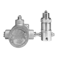
assembly
Slide the thermistor/heater assembly through the open leg of the condulet. Continue inserting the thermistor/
heater assembly until it is firmly seated against the bottom of the bore (refer to the drawing). Failure to do this will
cause improper heating of the unit and could lead to failure of the unit.
Place the sub-plate over the wires of the thermistor/heater assembly and leave the spade connectors extending up
as indicated in the drawing. Be careful not to crimp or pinch the wires under the plate. Pull up enough slack in the
wires to facilitate the connection to the terminal strip, but DO NOT pull the thermistor/heater assembly away from
the bottom of the bore. The wires must be run under the sub-plate to prevent damaging them when the condulet
cap is installed.
Using the two screws, tighten the sub-plate onto the condulet.
Using the two outside screws for the terminal strip, tighten it onto the sub-plate.
Insert the controller onto the middle four leads, making sure the AC standoffs will be on terminals 2 and 4.
Carefully feed the spade connectors onto the correctly numbered terminals. Failure to match up the numbered
leads with the right terminal will cause failure of the unit and pose a risk of injury to the technician.
Tighten the screws and standoffs down.
Feed in the AC power supply and connect to the top of the standoffs located at terminals 2 and 4.
Connect the ground wire to either the internal GREEN grounding screw, or to the external GREEN grounding screw.
Failure to properly ground this unit will pose a safety hazard.
Screw down the condulet cap and tighten.
1.
2.
3.
4.
5.
6.
7.
8.
9.
10.
GO Regulator
405 Centura Court • PO Box 4866 • Spartanburg, SC 29303
Phone (864) 574-7966 • Fax (864) 574-5608
www.goreg.com • sales@goreg.com

 Loading...