PAGE 12 updated 19/01/06
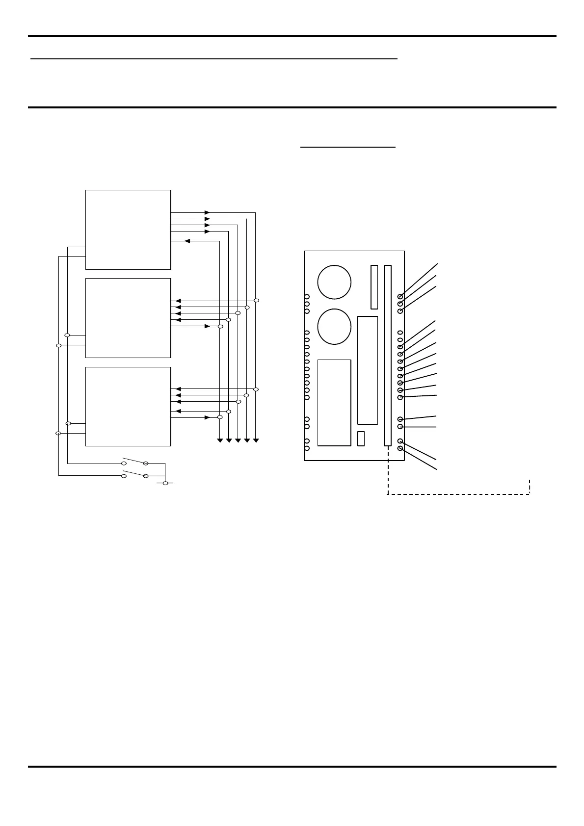
Bus board connections
The diagram below illustrates how Master and Slave
sound stores are connected together in synchronised
multi-track applications.
NEST UNIT SYSTEM
When multiple sound stores are required, boards can be
housed in a 3U nest unit. All required connections are
presented to a bus board as detailed below.
Synchronisation multi-track applications
DMS3000 V2.20
Digital Audio Playback Card
Golding Audio Ltd
Unit 8
Peartree Business Centre
Stanway Colchester
Essex CO3 0JN
Tel: 01206 762462 Fax: 01206 762633
Web Site: www.goldingaudio.co.uk
Golding Audio Ltd reserve the right to change specification of this or any product without prior notice being given. Golding Audio will not be held
responsible for any damage caused to any equipment or data, arising from use of the product mentioned herein.
MASTER BOARD
SYSCLK
FRMCLK OUT
SYNC OUT
RUN OUT
SYNC IN
TRIP 1
STOP
SLAVE BOARD
SYSCLK
F R M C L K IN
SYNC IN
RUN IN
SYNC OUT
TRIP 1
STOP
SLAVE BOARD
SYSCLK
F R M C L K IN
SYNC IN
RUN IN
SYNC OUT
TRIP 1
STOP
TRIP
STOP
Bus board connections
Trip1 A10
Start B14
Stop A14
frmclk in A16
frmclk out B16
sync in A17
run in B17
run out B18
sync out A18
sysclk +ve A19
sysclk -ve A20
Logic Gnd A/B28
5V output A/B29
Gnd in A/B31
15v in A/B32
 Loading...