PAGE 2 updated 19/01/06
DIN41612 connection details.
Creating MP3 files.
STEP 1
The usual way to create a .mp3 file is to record the soundtrack into the
computer as a wav file using software such as “Adobe Audition”
STEP 2
Next edit the wav file so that any unnecessary silence is removed from
the start and end of the soundtrack. All editing must be carried out while
the file is still in a .wav format as it is not practical to edit an .mp3 file.
STEP 3
The third step is to encode the wav file to an mp3 file using “Audition” or
similar encoder. It is this point that determines the quality of the finished
mp3 file by selecting the most appropriate bit rate for the file. The lower
the bit rate, the lower the quality and bandwidth of the output file but a
lower bit rate would use less memory per second.
The usual bit rate for encoding mp3 files is 128Kbits per second which
will provide a bandwidth of 20Hz to 15KHz.
Example running times using a 32 Mbyte memory card.
Sample Rate Bit rate. Bandwidth. Running time.
44.1KHz 112Kbps = 20Hz to 13KHz = 38 Minutes
44.1KHz 128Kbps = 20Hz to 15KHz = 33 Minutes
44.1KHz 160Kbps = 20Hz to 18KHz = 26 Minutes
44.1KHz 192Kbps = 20Hz to 20KHz = 22 Minutes
Memory Card (MMC)
The DMS3000 currently supports MMC cards from 64MB to 1GB . We
can supply fully compatible cards which we recommend as some makes
of card are not compatible. Cards must be formatted with FAT16 only.
The MMC card used with the DMS3000 sound store must contain certain
files and directories to operate. These files are detailed below.
ROOT files and Directories.
Files named CFG.txt (configuration data) and CTL?name.txt (control
data) must be present in the ROOT DIRECTORY. A subdirectory named
DATA must also be present to hold your .mp3 sound files and any com-
mand.txt file associated with any particular trip input.
CFG.txt
contains Configuration data for the DMS3000 chip set. This file
is set as READ ONLY and MUST NOT BE MODIFIED.
CTL?name.txt
contains user settable parameters for the sound store
such as trip input conditioning, tone control presets, RS485 addressing
etc. the full list of available control commands are described later.
DATA SUB DIRECTORY
This Directory must contain all .mp3 sound files and any command files
you require.
.mp3 Sound files. Must be named in the following manner to enable
the sound store to identify message files.
The first 3 digits in the file name assign the message to it’s trip input
number, messages 001 to 255 are available.
The next string of characters are used for your message name if re-
quired, the first 16 of these characters will be displayed on the 2x16 LCD
display if fitted.
File Extension the last 4 characters MUST ALWAYS BE .mp3 for a
valid file name.
Example 1, 001TEST MESSAGE.mp3
Example 2, 156This is a test.mp3
Both the above are valid file names for messages 1 and 156.
Command files
If required a command text file can be written and assigned to any trip
input to provide access and control over any or all .mp3 sound files pre-
sent in the DATA directory. Command files enable you to use features
such as message selection / playback, delay timers, message sequenc-
ers, trip conditioning, random message selection etc (see command file
section). An example command file name assigned to trip input 1 would
be 001?name.txt When tripped command files take priority over
any .mp3 sound file with the same message number.
eg. 001?name.txt would have priority over 001?name.mp3 however
message 001?name.mp3 could still be played from within the command
file.
Connection and General information
DMS3000 V2.20
Digital Audio Playback Card
Golding Audio Ltd
Unit 8
Peartree Business Centre
Stanway Colchester
Essex CO3 0JN
Tel: 01206 762462 Fax: 01206 762633
Web Site: www.goldingaudio.co.uk
Golding Audio Ltd reserve the right to change specification of this or any product without prior notice being given. Golding Audio will not be held
responsible for any damage caused to any equipment or data, arising from use of the product mentioned herein.
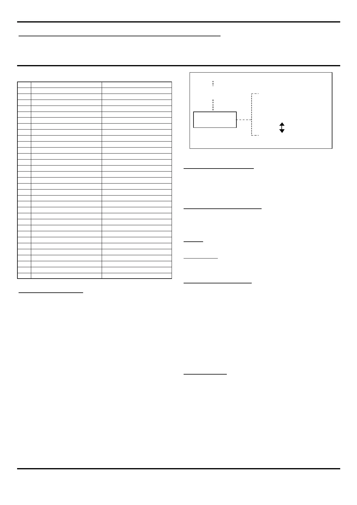
DATA
Directory
CARD ROOT
C FG.txt
C TL.txt
001?name.mp3
002?name.mp3
005?name.txt
128?name.mp3
205?name.txt
255?name.mp3
FIG 2
Pin ROW B ROW A
1 Audio Line OUT Ch1 LEFT Audio Line OUT Ch1 LEFT
2 Gnd Analogue Gnd Analogue
3 N/C N/C
4 Audio Line OUT Ch2 RIGHT Audio Line OUT Ch2 RIGHT
5 Gnd Analogue Gnd Analogue
6 N/C N/C
7 N/C N/C
8 N/C N/C
9 N/C N/C
10 TRIP 2 - INPUT TRIP 1 - INPUT
11 TRIP 4 - INPUT TRIP 3 - INPUT
12 TRIP 6 - INPUT TRIP 5 - INPUT
13 TRIP 8 - INPUT TRIP 7 - INPUT
14 START Line STOP Line
15 RS485 + reserved RS485 - reserved
16 FRAME CLOCK-OUT FRAME CLOCK-IN
17 RUN-IN SYNC-IN
18 RUN-OUT SYNC-OUT
19 CONTROL-OUT RS485 + Remote or sys clock
20 Logic supply 12-18v RS485 - Remote or sys clock
21 0v IN Logic Logic supply 12-18v
22 0v IN Logic N/C
23 N/C N/C
24 N/C N/C
25 N/C N/C
26 Gnd Analogue Gnd Analogue
27 N/C N/C
28 0v Logic 0v Logic
29 5v OUT 5v OUT
30 0v Logic 0v Logic
31 0v IN Logic 0v IN Logic
32 Logic supply 12-18v Logic supply 12-18v
 Loading...