EasyManua.ls Logo

Goodman ASX User Manual

Goodman ASX
80 pages
To Next Page IconTo Next Page
Page #1 background imageLoading...
Page #1 background image
RS6200006r11
April 2009
This manual is to be used by qualified, professionally trained HVAC techni-
cians only. Goodman does not assume any responsibility for property
damage or personal injury due to improper service procedures or services
performed by an unqualified person.
Copyright © 2006 - 2009 Goodman Manufacturing Company, L.P.
SSX, ASX, GSX, DSX Condensing Units,
SSZ, ASZ, GSZ DSZ Split System Heat Pumps
with R-410A Refrigerant
Blowers, Coils, & Accessories
Service Instructions

Table of Contents

Question and Answer IconNeed help?

Do you have a question about the Goodman ASX and is the answer not in the manual?

Goodman ASX Specifications

General IconGeneral
BrandGoodman
ModelASX
CategoryHeat Pump
LanguageEnglish

Summary

Service Instructions

Important Information

Important Notices for Consumers and Servicers

Key warnings and safety notices for users and technicians.

Safe Refrigerant Handling

Guidelines and precautions for safe handling of refrigerants.

Product Identification

Accessories

Product Design

Condensing Unit

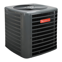
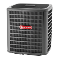
Description of the condenser unit's components and operation.

Coils and Blower Coils

Details on evaporator coils, blower cabinets, and their configurations.

Capacity Control

Explanation of how the system controls its operational capacity.

Unloader Solenoid

Function and operation of the unloader solenoid in capacity control.

System Operation

Cooling

Explanation of the system's cooling cycle and refrigerant flow.

Heating

Description of the system's heating cycle and refrigerant flow reversal.

Cooling Cycle

Step-by-step process of the cooling cycle operation.

Defrost Cycle

How the system manages defrosting to prevent ice buildup.

Troubleshooting Chart

Cooling/HP Analysis Chart

Guide to diagnose cooling and heat pump system issues.

Servicing

S-1 Checking Voltage

Procedure for verifying electrical voltage supply to the unit.

S-2 Checking Wiring

Steps for inspecting wiring for damage and continuity.

S-3 Checking Thermostat, Wiring, and Anticipator

How to check thermostat and wiring for correct operation.

S-4 Checking Transformer and Control Circuit

How to test the control transformer and associated circuits.

S-10 Copeland Comfort Alert TM Diagnostics

Using the Comfort Alert system for diagnosing compressor issues.

S-100 Refrigeration Repair Practice

General guidelines and safety for refrigeration system repairs.

S-110 Checking Expansion Valve Operation

Procedure to test the functionality of the expansion valve.

Accessories Wiring Diagrams

All Fuel System AFE18-60A Control Board

Wiring diagram for the AFE18-60A control board.

10kw and Below, One Stage Electric Heat

Wiring schematic for electric heat kits (10kW and below).

15kw and Above, Two Stage Electric Heat

Wiring schematic for electric heat kits (15kW and above).

Related product manuals