6
Electrical Connections
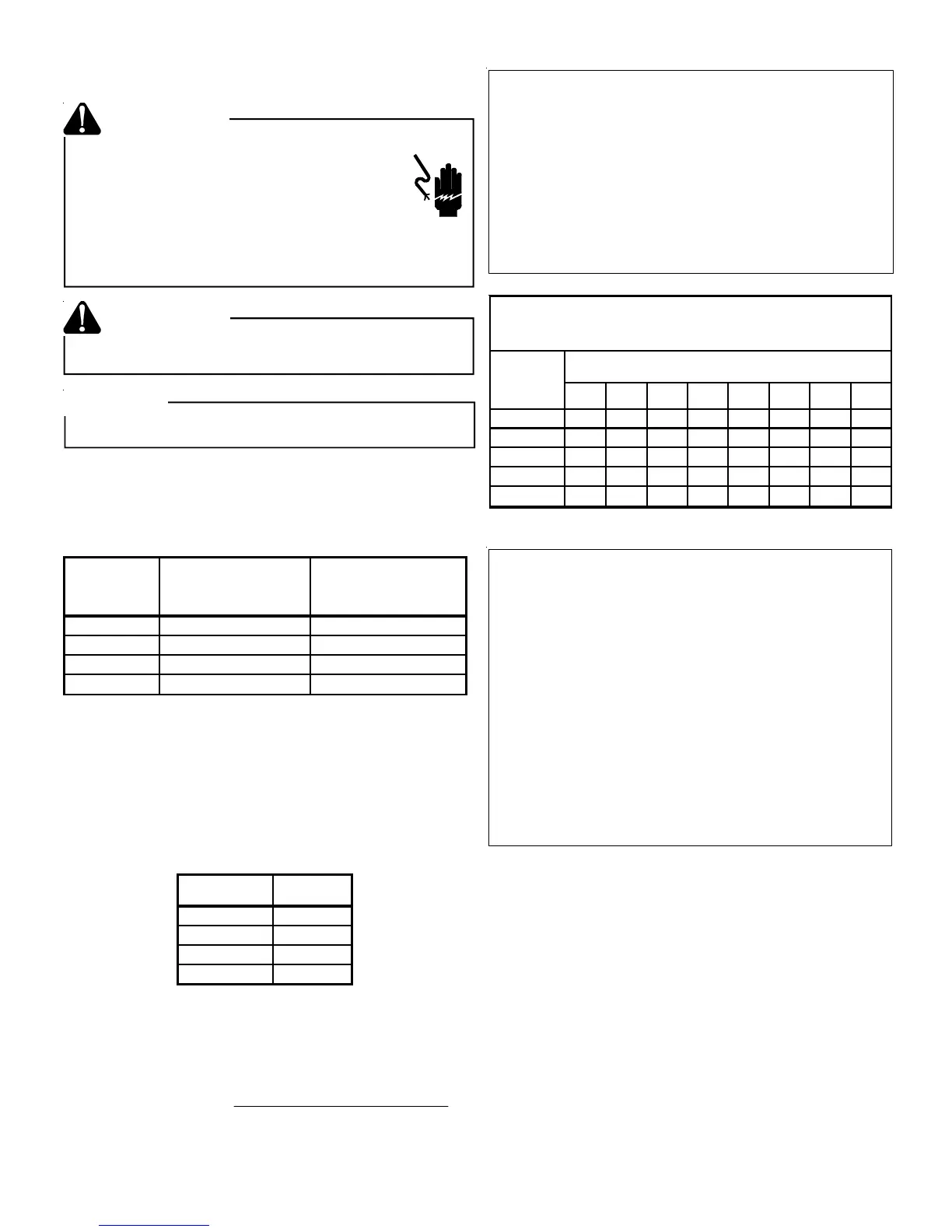
HIGH VOLTAGE!
Disconnect ALL power before servicing.
Multiple power sources may be present.
Failure to do so may cause property damage,
personal injury or death due to electric shock.
Wiring must conform with NEC or CEC and all
local codes. Undersized wires could cause
poor equipment performance, equipment damage
or fire.
WARNING
To avoid the risk of fire or equipment damage, use
copper conductors.
WARNING
NOTICE
Units with reciprocating compressors and non-bleed TXV’s
require a Hard Start Kit.
This unit is designed for three phase operation. DO NOT
OPERATE ON A SINGLE PHASE POWER SUPPLY. Mea-
sure the power supply to the unit. The supply voltage must
be in agreement with the unit rating plate power require-
ments and within the range listed below:
MODEL
MINIMUM SUPPLY
VOLTAGE
MAXIMUM SUPPLY
VOLTAGE
GSH100903 197 253
GSH100904 414 506
GSH101203 197 253
GSH101204 414 506
The condensing unit rating plate lists pertinent electrical data
necessary for proper electrical service and overcurrent pro-
tection. Wires should be sized to limit voltage drop to 2%
(max.) from the main breaker or fuse panel to the condens-
ing unit. Consult the NEC, CEC, and all local codes to de-
termine the correct wire gauge and length. The wire size
must be sufficient to carry the Minimum Circuit Ampacity
(MCA) listed on the serial plate and the following table:
MODEL MCA
GSH100903 37.6
GSH100904 18.7
GSH101203 43.2
GSH101204 22.1
The supply voltage can be unbalanced (phase to phase)
within 2%. The following formula can be used to determine
the percentage of voltage unbalance for your unit.
Percentage
Voltage
Unbalance
=
100 x
Max. Voltage Deviation Form
Average Voltage
Average Voltage
Example:
L1-L2 = 220V
L2-L3 = 216V
Average Voltage = (220 + 216 + 213)/3
=649/3
Maximum Deviation from Average = 220 - 216 = 4
% Voltage Unbalance = 100 x (4/216)
= 400/216
10 15 20 25 30 35 40 45
14 75 50 37 NR NR NR NR NR
12 118 79 59 47 NR NR NR NR
10 188 125 95 75 63 54 NR NR
8 301 201 150 120 100 86 75 68
6 471 314 235 188 157 134 118 110
*Based on NEC 1996
MAXIMUM ALLOWABLE LENGTH IN FEET
TO LIMIT VOLTAGE DROP TO 2%
Minimum Circuit Ampacity (MCA)
Wire Size
(AWG)
Example:
A GSH100903 is to be installed. The distance from the
building to the unit is 75’. Calculate the minimum wire size
assuming no more than 2% voltage drop.
MCA for GSH100903 = 43.3 (from S& R plate and table).
Applying previous table wire sizes less than #8 AWG
cannot be used for circuits which have a rating of 45A.
The #8 wire is not suitable since the maximum length for
a 45A circuit is 68’.
Solution: Use a #6 AWG wire suitable up to 110’.
NOTE: It is the contractors’s responsibility to follow the
NEC(USA) or CEC (Canada) when sizing the service wire
for this unit.
Local codes often require a disconnect switch located near
the unit; do not install the switch on the unit. Refer to the
installation instructions supplied with the indoor furnace/air
handler for specific wiring connections and indoor unit con-
figuration. Likewise, consult the instructions packaged with
the thermostat for mounting and location information.
Overcurrent Protection
The following overcurrent protection devices are approved
for use.
• Time delay fuses
• HACR type circuit breakers
These devices have sufficient time delay to permit the motor-
compressor to start and accelerate its load.