13
PRODUCT DESIGN
Disposable Minimum Filter Area (in
2
)
[Based on a 300 ft/min filter face velocity]
*Minimum filter area dictated by heating airflow requirement.
*Minimum filter area dictated by heating airflow requirement.
Permanent Minimum Filter Area (in
2
)
[Based on 600 ft/min filter face velocity]
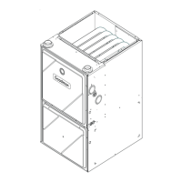
Counterflow Filters
This furnace has provisions for the installation of return air filters at the counterflow top return. The furnace will accommodate
the following filter sizes depending on cabinet size:
Refer to Minimum Filter Area tables to determine filter area requirement. NOTE: Filters can also be installed elsewhere
in the duct system such as a central return.
Cabinet Width
Filter Area
(in
2
)
Qty
Filter Size
(in)
Dimension "A"
(in)
17 1/2 14.2
21 13.0
24 1/2 11.3
17 1/2 19.7
21 18.8
24 1/2 17.7
17 1/2 25.0
21 24.3
24 1/2 23.4
Counterflow Top Return
600 2 15 X 20 X 1
800 2 20 X 20 X 1
1000 2 25 X 20 X 1
Return Air
Optional
Access
Door
600 800 1000 1200 1400 1600 2000
0453__X* 415* 415* 480 576 --- --- ---
0704__X* --- --- 636* 636* 672 768
0905__X* --- --- --- 826* 826* 826* 960
1155__X* --- --- --- 875* 875* 875* 960
600 800 1000 1200 1400 1600 2000
0704__X* --- --- 634* 634* 672 768 ---
0905__X* --- --- --- 819* 819* 819* 960
115__X* --- --- --- 860* 860* 860* 960
Input__Airflow
UPFLOW
COOLING AIRFLOW REQUIREMENT (CFM)
COUNTERFLOW
COOLING AIRFLOW REQUIREMENT (CFM)
Input
Airflow
600 800 1000 1200 1400 1600 2000
0453__X* 207* 207* 240 288 --- --- ---
0704__X* --- --- 318* 318* 336 384 ---
0905__X* --- --- --- 413* 413* 413* 480
1155__X* --- --- --- 437* 437* 437* 480
600 800 1000 1200 1400 1600 2000
0704__X* --- --- 316* 316* 336 384 ---
0905__X* --- --- --- 409* 409* 409* 480
1155__X* --- --- --- 430* 430* 430* 480
Input__Airflow
UPFLOW
COOLING AIRFLOW REQUIREMENT (CFM)
COUNTERFLOW
COOLING AIRFLOW REQUIREMENT (CFM)
Input
Airflow
 Loading...