9
For Natural gas to LP gas conversion,
Conversion Kit “LPM-08” must be used. Consult your dealer
All propane gas equipment must conform to the safety stan-
For satisfactory operation, propane gas supply pressure
must be within 9.7 - 10.3 inches W.C. at the manifold with all
gas appliances in operation. Maintaining proper gas pres-
sure depends on three main factors:
1.
or containers.
2. Proper pressure regulation.
3. Pressure drop in lines between regulators, and be-
tween second stage regulator and the appliance. Pipe
size required will depend on length of pipe run and total
load of all appliances.
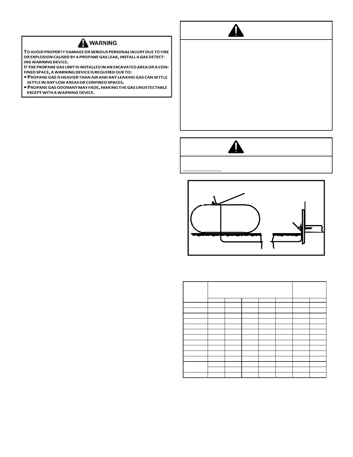
Complete information regarding tank sizing for vaporization,
recommended regulator settings and pipe sizing is available
from most regulator manufacturers and propane gas suppliers.
Since propane gas will quickly dissolve white lead or most
standard commercial compounds, special pipe dope must
be used. Shellac base compounds resistant to the actions
Clyde’s® or John Crane® are satisfactory.
arrangement.
IG
m
IG
IG
Sizing Between First and Second Stage Regulator
Maximum Propane Capacities listed are based on 1 PSIG Pressure Drop at 10
PSIG Setting. Capacities in 1,000 BTU/HR
3/8" 1/2" 5/8" 3/4" 7/8" 1/2" 3/4"
30 309 700 1,303 2,205 3,394 1,843 3,854
40 265 599 1,115 1,887 2,904 1,577 3,298
50 235 531 988 1,672 2,574 1,398 2,923
60 213 481 896 1,515 2,332 1,267 2,649
70 196 446 824 1,394 2,146 1,165 2,437
80 182 412 767 1,297 1,996 1,084 2,267
90 171 386 719 1,217 1,873 1,017 2,127
100 161 365 679 1,149 1,769 961 2,009
150 130 293 546 923 1,421 772 1,613
200 111 251
467 790 1,216 660 1,381
250 90 222 414 700 1,078 585 1,224
300 89 201 378 634 976 530 1,109
350 82 185 345 584 898 488 1,020
400 76 172 321 543 836 454 949
To convert to Capacities at 15 PSIG Settings -- Multiply by 1.130
To convert to Capacities at 5 PSIG Settings -- Multiply by 0.879
PIPE OR
TUBING
LENGTH,
FEET
NOMINAL PIPE SIZE,
SCHEDULE 40
TUBING SIZE, O.D., TYPE L
 Loading...