INSTRUCCIONES DE ENSAMBLAJE
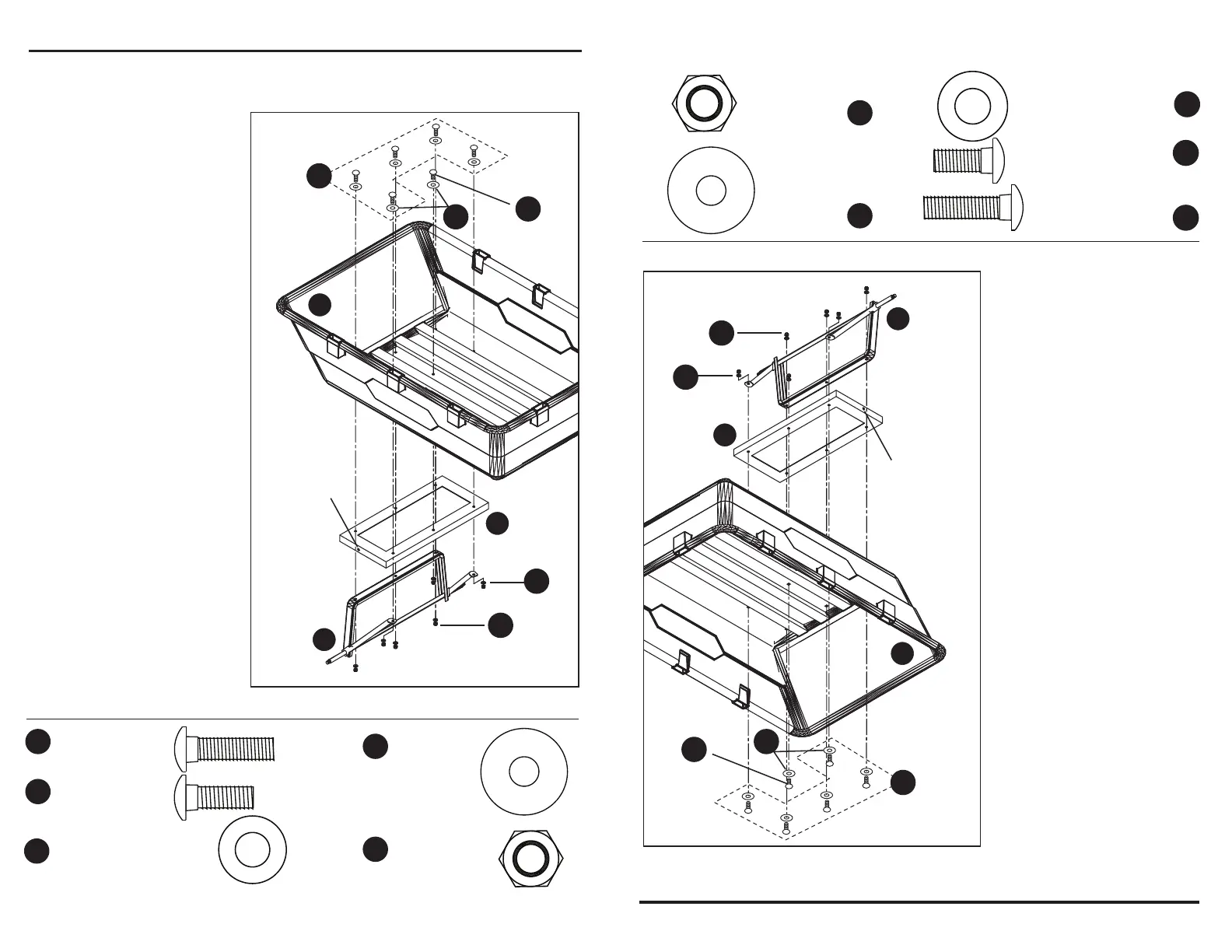
5. Fije el ensamble del eje
posterior (E) con los puntales
posteriores (C) y la estructura
posterior (D) a la bandeja (A)
con pernos cabeza de hongo
M8 x 38 mm (BB), un pernos
cabeza de hongo M8 x 35 mm
(CC), seis contratuercas M8
(KK), seis arandelas M11
(HH), y seis arandelas M8
(GG), como se muestra en la
Fig. 7.
Use el pernos cabeza de
hongo M8 x 35 mm (CC) en la
parte central delantera de la
estructura posterior (D), como
se muestra en la Fig. 7.
6
Fig. 7
Aditamentos utilizados
El orificio más
cercano a la parte
posterior de la
bandeja
Consulte las
paso 4, fig. 5
para confirmar
que la colocación
esta correcto
El frente
de la
bandeja
M8 x 20mm
pernos cabeza
de hongo
x 5
x 1
x 6
M8 x 25mm
pernos cabeza
de hongo
Arandela plana M8
CC
BB
GG
A
D
E
KK
CC
HH
BB
GG
x 6
KK
Contratuerca
M8
x 6
HH
Arandela
plana M11
ASSEMBLY INSTRUCTIONS
Fig. 7
Hardware Used
5. Attach the rear axle
assembly (E) with the rear
struts (C) and the rear frame
(D) to the tray (A) using five
M8 x 38 carriage bolts (BB),
one M8 x 35mm carriage
bolts (CC), six M8 lock nuts
(KK), six M11 washers (HH),
and six M8 washers (GG), as
shown in Fig. 7.
Use the one M8 x 35mm
carriage bolts (CC) in the
front center location of the
rear frame (D), as shown in
Fig. 7.
6
x 5
x 1
x 6
x 6
M8 Flat
Washer
KK
CC
M8 Lock Nut
x 6
HH
M11 Flat
Washer
BB
GG
M8 x 35mm
Carriage Bolt
M8 x 38mm
Carriage Bolt
Hole
Closer
to rear
of tray
Front
of tray
A
D
E
KK
CC
HH
BB
GG