Do you have a question about the Gossen MetraWatt SSP 240-40 and is the answer not in the manual?
Critical warnings covering protective grounding, impaired safety, housing panel access, repair, and fuse replacement.
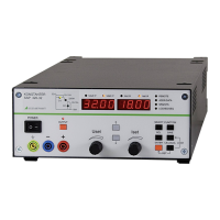
Overview of device capabilities, applications, and suitability for various electrical conditions.
Lists adjustable, display, and protective functions of the KONSTANTER series.
Explanation of power supply, central processing unit, operation, and interface control.
Details power supply, input/output connections, analog and RS 232 interfaces, and output operating range.
Details safety class, overvoltage category, fouling factor, and earth leakage current.
Detailed electrical specifications for 120W models, including output characteristics and protective functions.
Detailed electrical specifications for 240W and 320W models.
Covers installing interface modules, rack mounting, combining devices, and connecting power and computer interfaces.
Procedure for switching the instrument on and the power-up test routine.
How to initialize the device with factory default settings using a specific key combination.
Function of the main power switch and the output on/off key, including activation/deactivation sequences.
Explanation of LEDs indicating operating status, control mode, and reasons for output deactivation.
Details on output terminals, left/right displays, parameter LEDs, and adjustment knobs.
Details on current adjustment knob, parameter keys, interface LEDs, function keys, and interface connections.
Explains the analog interface functions and the output interface options.
Overview of the basic operating mode and navigating setup menus using function keys.
Explains direct selection and pre-selected setting methods for voltage and current.
Procedure for activating/deactivating the power output using the OUTPUT key.
Setting voltage and current limits to match the power consumer's working range.
Explanation of overvoltage protection (OVP) and overcurrent protection (OCP).
Setting the trigger value for overvoltage protection.
Function to protect against continuous overcurrent by deactivating the output.
Allows automated execution of stored setpoints and manages memory locations for sequences.
Controlling automatic sequence recall and setting sequence status.
Step-by-step guide for setting all values required for a sequence.
Assigning a unique address to the KONSTANTER for communication on the IEC bus.
How to switch between manual (local) and remote control modes.
Details pin assignments for analog interface signals and outputs.
How to set output voltage using external control voltage via Uset inputs.
How to set output current using external voltage via Iset input.
Connecting multiple KONSTANTERs in parallel to increase output current.
Connecting devices in master-slave configuration for parallel operation, offering advantages over direct connection.
Instructions for connecting KONSTANTER outputs in series to increase output voltage.
Connecting devices in master-slave series configuration for precise voltage and current control.
Rules for command structure, including headers, parameters, abbreviations, and syntax elements.
Alphabetical listing and description of setting, query, and interface commands.
Resetting device settings to factory defaults.
Transferring parameters directly to memory locations, overwriting existing data.
Table summarizing settings and query commands by application type.
Saving current device settings to SETUP or SEQUENCE memory.
Controlling automatic sequence recall and setting sequence status.
Explains the meaning of various register contents like TCE, CCR, CME, EXE, etc.
Steps for preparing and connecting measuring instruments for voltage and current adjustment.
Connecting interfaces and using commands for PC-aided adjustment.
Table of adjustable functions, their commands, significance, and settings.
Table of functions and parameters that can be queried via interface, including response strings.
Table of query commands for status and event registers (CRA, ERA, ERB, etc.).
Diagram illustrating the device's memory structure, including default settings, SETUP, sequence, and min-max memory.
Table detailing operating states, linked functions, LED indications, and display functions.
List of system error messages, their meaning, cause, and remedy.
| Frequency | 50/60 Hz |
|---|---|
| Operating Temperature | 0°C to 40°C |
| Storage Temperature | -20°C to 70°C |
| Input Voltage | 230 V AC |
| Protection Features | Overload, Short Circuit |
| Cooling | Forced air cooling |