ENGINE
GOVERNING
S
YSTEM
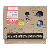
ESD5500E Series
Speed Control Unit
Governors America Corp., 720 Silver Street Agawam, MA 01001
phone: 413.786.5600 fax: 413.789.7736
www.governors-america.com
info@governors-america.com
1
O
MERICA
ORP.
C
A
®
ISO 9001
CERTIFIED
INSTALLATION
The speed control unit is rugged enough to be placed in
a control cabinet or engine mounted enclosure with other
dedicated control equipment. If water, mist, or condensation
may come in contact with the controller, it should be mount-
ed vertically. This will allow the fluid to drain away from the
speed control unit. Extreme heat should be avoided.
WIRING
Basic electrical connections are illustrated in Diagram 1. Ac-
tuator and battery connections to Terminals A, B, E, and F
should be #16 AWG (1.3 mm sq.) or larger. Long cables re-
quire an increased wire size to minimize voltage drops.
The battery positive (+) input, Terminal F, should be fused for
15 amps as illustrated.
Magnetic speed sensor wires connected to Terminals C and
D MUST BE TWISTED AND/OR SHIELDED for their en-
tire length. The speed sensor cable shield should ideally
be connected as shown in Diagram 1. The shield should be
insulated to insure no other part of the shield comes in con-
tact with engine ground, otherwise stray speed signals may
be introduced into the speed control unit. With the engine
stopped, adjust the gap between the magnetic speed sensor
and the ring gear teeth. The gap should not be any smaller
than 0.020 in. (0.45 mm). Usually, backing out the speed
sensor 3/4 turn after touching the ring gear teeth will achieve
a satisfactory air gap. The magnetic speed sensor voltage
should be at least 1 VAC RMS during cranking.
ADJUSTMENTS
Before Starting Engine
Check to insure the GAIN and STABILITY adjustments, and
if applied, the external SPEED TRIM CONTROL are set to
mid position.
Preset the ESD5500E as follows:
STARTING FUEL FULL CW(Maximum Fuel)
SPEED RAMPING FULL CCW(Fastest)
Start Engine
The speed control unit governed speed setting is factory set
at approximately engine idle speed. (1000 Hz., Speed sen-
sor signal)
Crank the engine with DC power applied to the governor sys-
tem. The actuator will energize to the maximum fuel position
until the engine starts. The governor system should control
the engine at a low idle speed. If the engine is unstable after
starting, turn the GAIN and STABILITY adjustments counter-
clockwise until the engine is stable.
Governor Speed Setting
The governed speed set point is increased by clockwise
rotation of the SPEED adjustment control. Remote speed
adjustment can be obtained with an optional 5K Speed Trim
Control. (See Diagram 1.)
Governor Performance
Once the engine is at operating speed and at no load, the
following governor performance adjustment can be made.
A. Rotate the GAIN adjustment clockwise until instability
develops. Gradually move the adjustment counterclock-
wise until stability returns. Move the adjustment one
division further counterclockwise to insure stable perfor-
mance (270° pot).
B. Rotate the STABILITY adjustment clockwise until insta-
bility develops. Gradually move the adjustment counter-
clockwise until stability returns. Move the adjustment one
division further to insure stable performance (270° pot).
C. Gain and stability adjustments may require minor chang-
es after engine load is applied. Normally, adjustments
made at no load achieve satisfactory performance. A
strip chart recorder can be used to further optimize the
adjustments.
If instability cannot be corrected or further performance
improvements are required, refer below to the SYSTEM
TROUBLESHOOTING section.
Starting Fuel Adjustment
The engine’s exhaust smoke at start-up can be minimized by
completing the following adjustments:
1. Place the engine in idle by connecting Terminals M & G.
2. Adjust the IDLE speed for as low a speed setting as the
application allows.
3. Adjust the STARTING FUEL CCW until the engine speed
begins to fall. Increase the STARTING FUEL slightly so
⚠WARNING
An overspeed shutdown device, independent of
the governor system, should be provided to pre-
vent loss of engine control, which may cause per-
sonal injury or equipment damage. Do not rely
exclusively on the governor system electric ac-
tuator to prevent overspeed. A secondary shutoff
device, such as a fuel solenoid, must be used.