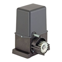
POSITIONING OF BASEMENT PLATE
- Make a foundation pit in order that the foundation plate is
78 mm far from the GATE (not from the slide).
- Put the plate in the foundation pit (protect the inferior part
of the camping screws holes).
- In positioning the foundation pit, make sure that the plate
hole for passage of cables is in opposite side of the gate
(see photo).
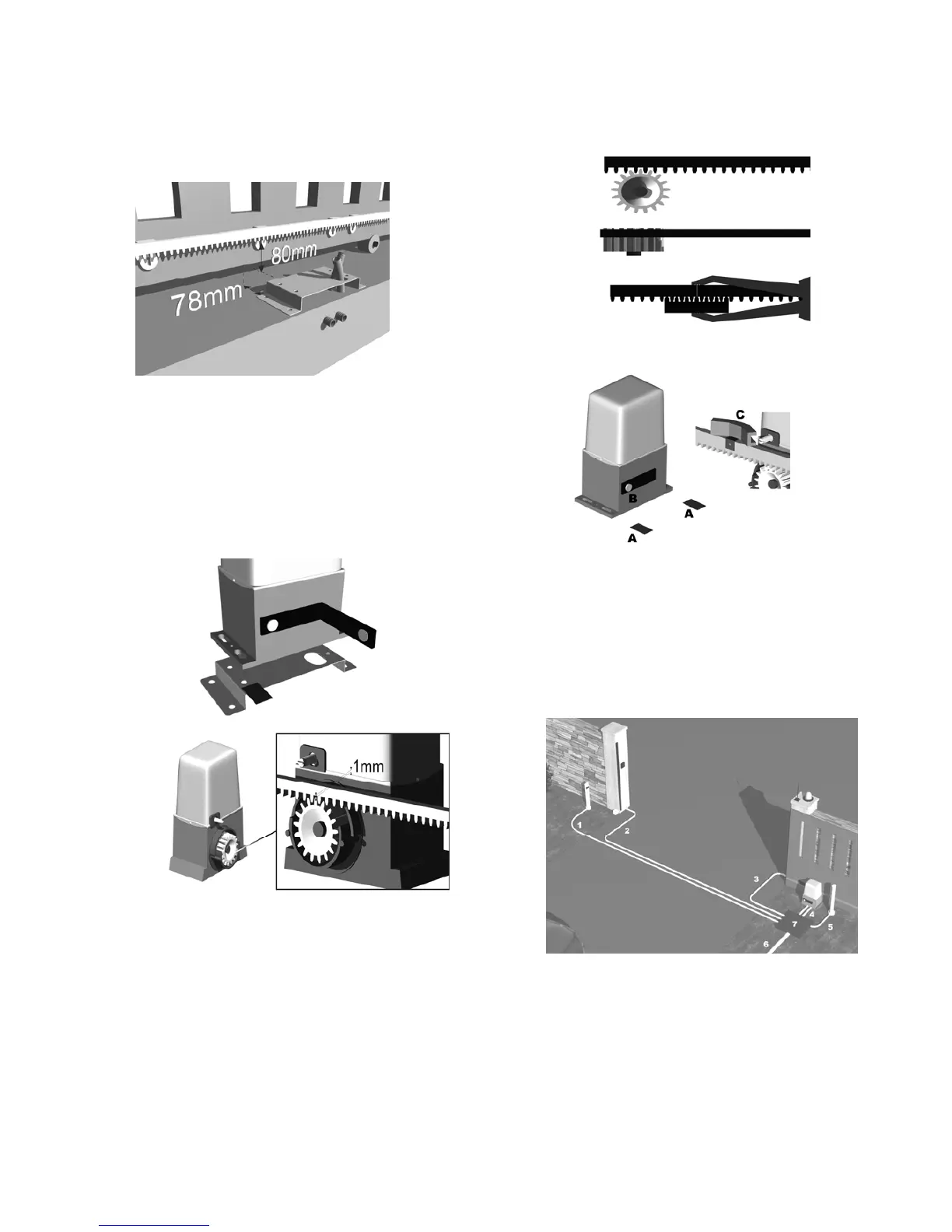
POSITIONING OF THE MOTOR
- Put the motor on the plate.
- Put 4 little shims between the motor and the plate to keep
provisionally the motor 1 mm higher.
- Unclamp the motor by using lever (B). (Turn the lever of
100°).
Leave the lever open until the end of installation.
FIXING OF THE RACK
-Put the first piece of the rack on top of the spur wheel. And
make it run until point 1 (see Fig. 1)
-Weld or screw the first pin of the rack to the gate.
-Add all the other pieces of the rack in order they are perfectly
aligned to the first.
FINAL OPERATION
- Take out from the bottom of the motor the 4 shims and
fix the motor to the foundation plate using screws.
- Shift manually the gate and fix on the rack the end run
cams (C).
- Clamp the lever. (A)
- Apply the electric connections.
- Fix the carter.
- Control the perfect working of the motor.
ELECTRICAL CONNECTIONS
1 - tube d. 20 mm. – cable for rx photocell 2x0.5 mm.
2 - tube d. 20 mm. – cable for rx photocell 2x0.5 mm. -
Cable for electromechanical sensing device 2x0,5 mm.
3 - tube d. 0.25 mm – cable for tx photocell 4x0,5 -
Cable for flashing light 3x0,5 – cable for Electromechanical
sensing device 2x0,5 mm. - Cable for key switch 3x0,5 mm. -
Cable for antenna Rg59
4 - 2 tube d. 0.25 mm. For cables to the motor
5 - tube d. 0.20 mm. – cable for tx photocell 4x0.5 mm.
6 - tube d. 0.60 – alimentation cable 3x1.5 mm.
7 - shaft
A
 Loading...