Repair Manual MSG 90.6PG Commercial Vehicles, Omnibuses – November 2017
Material no. 1153450_c
2.1 Overview of components
Page 2 of 15
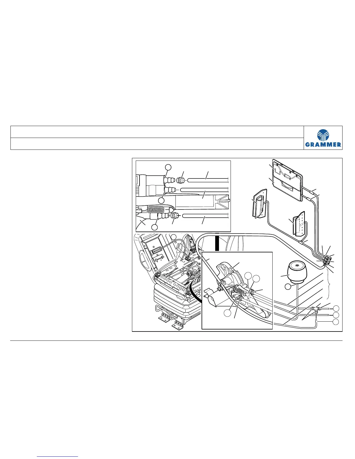
Pneumatic connecting diagram
(1) Air hose (blue) for air spring (Z)
(2) Air hose (black) for air intake (P)
(3) Air hose (gray) for air exhaust (R)
(4) Air hose (black) for lumbar support
and lateral support adjustment (A)
(5) Entire air hose set
= (1) + (2) + (3) + (4)
Note:
The adhesive tapes are intended to
bundle the air hose set (5) and to
mark where the cable ties have to
be fastened.
(6) Air spring
(7) Hose connector (T-piece)
(8) Hose nozzle
(9) Level control
R
A
6
1
3
2
5
7
8
8
8
4
Z
10
11
12
13
14
14
14
17
16
15
18
18
18
4
P
9
4
P
R
8
8
Z
2259
8 2
3
189
P
Z
R