Find the magnetic (mag) pickup signal wire that you disconnected from the
old output jack, which will likely come from the centre contact of the existing
volume pot. Route the wire to the stereo jack and solder to the tip contact of
the jack.
Cut off the (unused) connector on the end of the dual connector from the
common connector block and solder the cable to the top contact of the new
volume pot (see Diagram 14, page 22, for pot contact key). The shield may be
connected to the bottom contact or the body of the pot.
Solder a shielded cable to the center contact of the new volume pot. The shield
may be connected to the body of the pot. Route the cable to the stereo jack.
Cut to length and solder to the ring contact of the jack. Solder the shield to the
ground contact of the jack.
Solder the capacitor between the top and centre contacts of the new volume
pot.
Solder a wire from the body of the new volume pot to ground (for example, the
body of another pot).
•
•
•
•
•
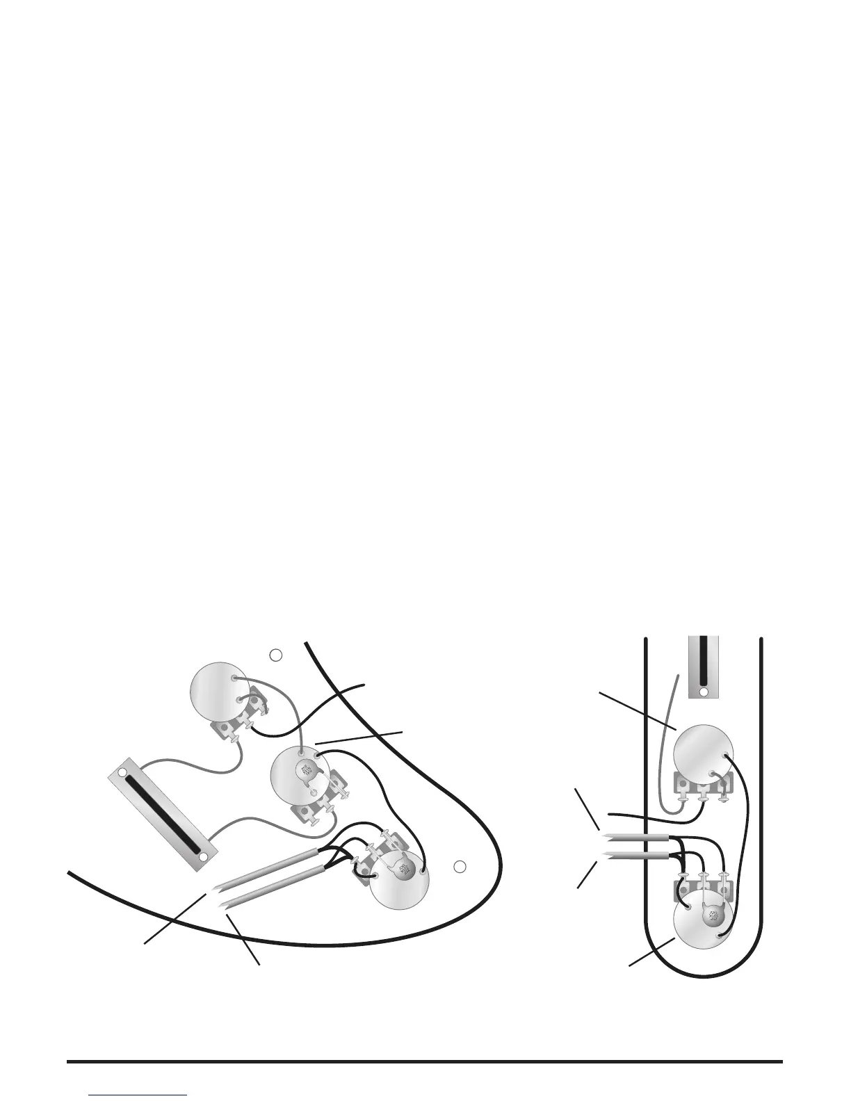
The wiring diagrams (Diagram 5) below show the GHOST volume pot installed
in place of an existing Tone control. For clarity, the wiring diagrams highlight the
new wires.
Magnetic
Volume
Magnetic
Tone
GHOST
Volume
GHOST
Pickups
Ring
Tip
Strat Style Instruments Tele Style Instruments
Tip
GHOST
Volume
Ring
GHOST
Pickups
Magnetic
Tone
Diagram 5.
 Loading...