11
handle after cutting, instead hold it slightly and allow the head to
return to the topmost position.
• Fix the material tightly in the vice (5).
• Switch on the portable cut off saw and wait until motor reaches its
full rotational speed.
• Use the handle (11) to press the head (19) downwards until the
cutting disc (3) slightly contacts the material to cut.
• Apply steady pressure on the head and make a cut (fig. F).
Do not reduce pressure at the end of a cut, otherwise the cut material
may get overheated and there may be uneven edges.
Do not allow vibrations or cutting disc bouncing on material, it
would adversely affect cut quality and may cause crack in the
cutting disc.
CUTTING LARGE PIECES
When fixing a wide piece of material, you can move the fixed jaw away
to increase distance between vice jaws.
• Set the head (19) in upper position.
• Unscrew the fixing screws for fixed jaw (17).
• Reinstall the fixed jaw (16) to holes located closer to the head arm
and attach by tightening the fixing screws for fixed jaw (17).
Number of cuts possible to do with cutting disc and quality may vary,
depending on the cutting speed. Fast cutting may cause early wear of
cutting disc, but protects the material against overheating and
ensures smooth cut surface.
SETTING THE VICE FOR MITRE CUTTING
The fixed jaw (16) also has a function of mitre gauge and allows to cut
material at any angle after adjustment within range from right angle
position to 450 left or right.
• Set the head (19) in upper position.
• Loosen the fixing screws for fixed jaw (17).
• Turn the fixed jaw (16) to required cutting angle accordingly to the
angle scale and secure position by tightening the fixing screws for
fixed jaw (17) loosened earlier (fig. G).
• Fix material in the vice and make a cut.
Even though the angle scale in fixed jaw is accurate enough for most
of performed tasks, it is recommended to double-check the cutting
angle with protractor or other device for angle measurements.
When fixing material in the vice, the sliding jaw (15) aligns itself in
parallel to fixed material, ensuring it is well secured.
OPERATION AND MAINTENANCE
Unplug the power cord from mains socket before commencing any
activities related to installation, adjustment, repair or maintenance.
• When the work is finished, remove thoroughly all pieces of material
and dust from the base and area around cutting disc and its shield.
• Clean the portable cut off saw with brush or stream of compressed
air.
• Never use water or other chemical liquids for cleaning the portable
cut off saw.
• Clean ventilation holes regularly to prevent motor overheating.
• Store the portable cut off saw in a dry place, beyond reach of
children.
• Entrust replacement of power cord and other repairs only to
authorized service workshop.
Regularly check that all bolts and fixing screws are tightened.
They may get loosened after some time of operation.
CUTTING DISC REPLACEMENT
• Set the head (19) in upper position.
• Place the movable shield for cutting disc (6) in its upper position.
• Loosen the nuts and take the side shield of the cutting disc (1) to the
back (fig. H).
• Push the spindle lock (20) in so the pin goes through the hole in the
movable shield for cutting disc (6) and turn the cutting disc (3) with
your hand until it locks.
• Use ring spanner (included) to unscrew the screw fixing cutting disc
(3) by turning it counter-clockwise (fig. I).
• Remove the screw fixing cutting disc, washer and outer collar, and
remove the cutting disc (3) carefully.
• Clean the collars thoroughly before installing a new cutting disc.
• Place new cutting disc and tighten its fixing screw, while holding the
spindle lock (20) pressed in.
• Release the spindle lock (20).
• Install the side shield for cutting disc (1) and tighten nuts.
• Use the handle (11) to move the head (19) downwards, so the
movable shield for cutting disc (6) is unlocked.
• Make sure the movable shield for cutting disc (6) operates correctly.
Use only recommended and reinforced cutting discs. Tighten
screw that fixes cutting disc, so the wheel is well clamped and
cannot rotate. When the cutting disc fixing screw is
overtightened, the wheel may get damaged.
REPLACEMENT OF CARBON BRUSHES
Replace immediately worn out (shorter than 5 mm), burnt or cracked
motor carbon brushes. Always replace both brushes at a time.
• Unscrew and remove carbon brush covers (7).
• Remove worn out carbon brushes.
• Remove any carbon dust with compressed air.
• Insert new carbon brushes. Brushes should easily move into brush-
holders.
• Fix carbon brush covers (7).
After the carbon brushes are replaced, start the portable cut off
saw with no load for approximately 2-3 minutes until the carbon
brushes fit to the motor commutator. It is recommended to
entrust replacement of carbon brushes only to a qualified person.
Only original parts should be used.
All faults should be repaired by service workshop authorized by the
manufacturer.
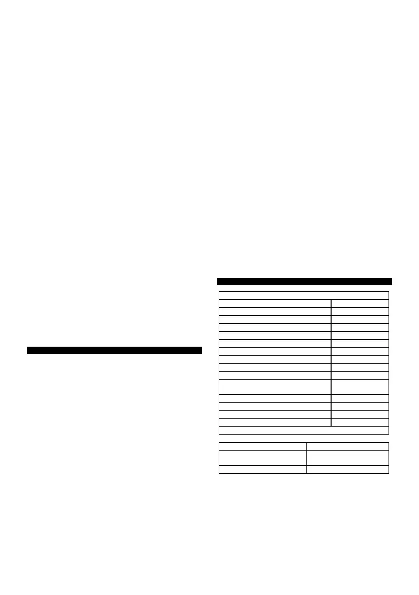
TECHNICAL PARAMETERS
Metal cutting machine 59G873
Blade rotational speed (without load)
Outer diameter of the disc
Inner diameter of the disc
Behind the cutting line at 90 ° (angle)
Cutting range at 90 ° (square profile)
Cutting range at 90 ° (rectangular
profile)
Cutting range at 90 ° (round profile)
5 9G873 means both machine type and machine description
NOISE AND VIBRATION DATA
L
PA
= 92.5 dB (A) K = 3 dB (A)
WA
= 105.5 dB (A) K = 3 dB
(A)
Information on noise and vibration
The level of noise emitted by the device is described by: the level of
emitted sound pressure Lp
A
and the level of acoustic power Lw
A
(where K is the measurement uncertainty). Vibration emitted by the
device is described by the value of vibration acceleration a
h
(where K
is the measurement uncertainty).
The level of emitted sound pressure Lp
A
, the sound power level Lw
A
and the value of vibration acceleration a
h
given in this manual were
measured in accordance with EN 62841-1. The given vibration level a
h
can be used to compare devices and to initially assess vibration
exposure.
The given vibration level is representative only for the basic
applications of the device. If the device is used for other applications
 Loading...