KARRERA K-FRAME — User Manual 19
K-Frame Control Surfaces
MEs available, as well as the number of video inputs, outputs, GPIOs and
Relay Tallies.
Figure 1. K-Frame Video Processors
K-Frame Control Surfaces
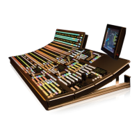
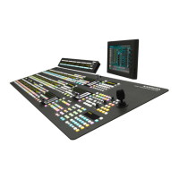
Karrera
A Karrera control surface typically consists of a Control Panel and a Menu
application. Representative Karrera control surfaces are shown in the fol
-
lowing illustrations.
Figure 2. Karrera 3-ME 35 Control Surface
Figure 3. Karrera 2-ME 25 Control Surface
8875_01
K-Frame 13-RU
Video Processor
K-Frame 6-RU
Video Processor
Frame Power Supply 1-RU
(1 for each K-Frame)
Optional Touch Screen
Karrera Menu Panel with
Fanless PC
Menu Panel
Articulated
Arm
8623266_02_Krr
Karrera 3-ME 35 Control Panel
8623266_03_Krr
Karrera 2-ME 25 Control Panel
Karrera Menu on PC
(Customer Supplied PC)
 Loading...