260 KARRERA — Installation & Service Manual
Section 7 — Maintenance
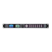
Control Panel Module Diagnostics
On Karrera panels, boot information/diagnostic is shown on the left most
character display of every panel board. This information (
Table 11) is
immediately visible after a power cycle and present until the application
software writes the first data to the character displays
Example codes are shows in Table 12
Creating Karrera Compact Flash Cards
The Karrera Video Processor Frame and Control Panel each use their own
specially formatted and partitioned Compact Flash (CF) card. The Karrera
Table 11. Control Panel Board Boot Display Codes
Digit
3 2 1 0
Digit Zero shows the link and FPGA boot status
*
1. Module interface link is working (normal/default).
2. FPGA was loaded over application area (normal/default).
+
1. Module interface link is working (normal/default).
2. FPGA was loaded over factory area: application area damaged, reprogramming necessary.
1. Module interface link is not working: link should come up after 1-3 seconds, if not there may be a hardware problem.
2. FPGA was loaded over application area (normal/default).
!
1. Module interface link is not working: link should come up after 1-3 seconds, if not there may be a hardware problem.
2. FPGA was loaded over factory area: application area damaged, reprogramming necessary!.
Digit 1 shows the lower number of the FPGA firmware version.
Digit 2 shows the middle number of the FGPA firmware version.
Digit 3 shows the upper number of the FPGA firmware version. (X1 always shows “!” to see the difference to the released versions).
Table 12. Control Panel Module Boot Display Codes Examples
Digit
0 3 7 *
1. Module interface link is working (normal/default).
2. FPGA was loaded over application area (normal/default).
3. FPGA firmware version is 037 (DS1281.037).
0 3 7 +
1. Module interface link is working (normal/default).
2. FPGA was loaded over factory area: application area damaged, reprogramming necessary.
3. FPGA firmware version is 037 (DS1281.037).
0 3 7
1. Module interface link is not working: link should come up after 1-3 seconds, if not there may be a hardware problem.
2. FPGA was loaded over application area (normal/default).
3. FPGA firmware version is 037 (DS1281.037).
0 3 7 !
1. Module interface link is not working: link should come up after 1-3 seconds, if not there may be a hardware problem.
2. FPGA was loaded over factory area --> application area damaged, reprogramming necessary.
3. FPGA firmware version is 038 (DS1281.038).
! 3 5 *
1. Module interface link is working (normal/default).
2. FPGA was loaded over factory area because X1 doesn't have a application area (normal/default).
3. FPGA firmware version is X1 and 35 (DS5831.035).
! 3 5
1. Module interface link is not working: link should come up after 1-3 seconds, if not there may be a hardware problem.
2. FPGA was loaded over factory area because X1 doesn't have a application area (normal/default).
3. FPGA firmware version is X1 and 35 (DS5831.038).
 Loading...