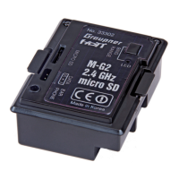
1. Open the module M-G2 with the two screws on the back. Open up the cover by folding it downward.
2. The module can now be installed in the transmitter: ensure that the connector contacts are correctly
positioned, otherwise they could be damaged when you plug the module in; do not use force! (Fig.
12 - 1)
3. The aerial connector can now be inserted in the socket on the module using no more than light pres-
sure. Ensure that it engages fully, i.e. there must be no chance of it coming loose when the system is
operating (Fig. 12 - 2).
4. Now all you have to do is re-attach the module cover: engage the two lugs in the left-hand side of the
module case, then fi t the two screws to secure it. Check that it is correctly located (Fig. 13).
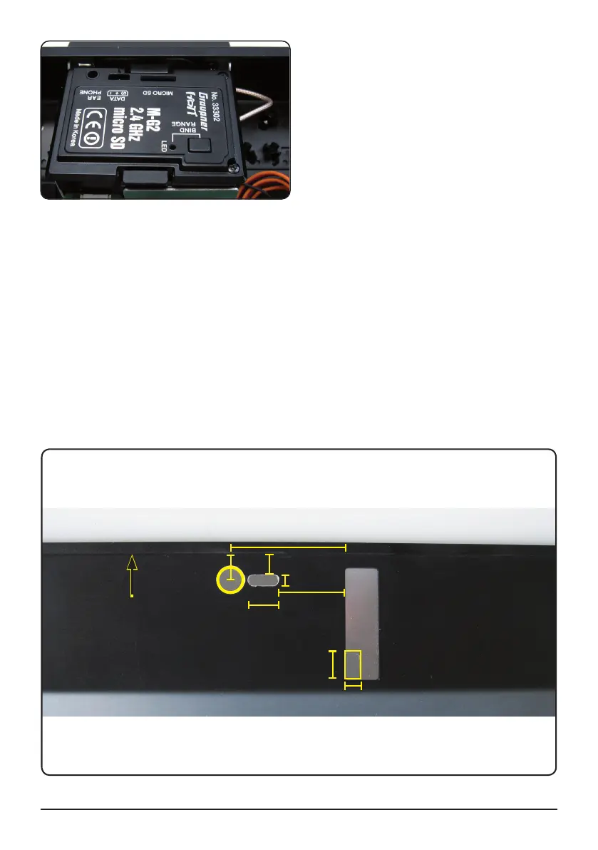
5. We recommend that you cut openings for the BIND / RANGE button, earphone socket and DATA
socket. The opening for the earphone socket is really essential, so that the earphones can conveni-
ently be inserted (Fig. 14).
6. Now all that remains is to re-attach the transmitter back panel.
7. Finally go to the transmitter „basic setup model“ menu and choose „modulation“ PPM 18 (for max. 9
servos) or PPM 24 (for max. 12 servos). Also when using the channel mapping with more than 9
channels choose PPM 24. JOB DONE!
Manual Module M-G2 33302 04
8
5
36
7
Ø 8
6
10
All dimensions in mm.
3
21
TOP
Fig. 14
Fig. 13