6
EN
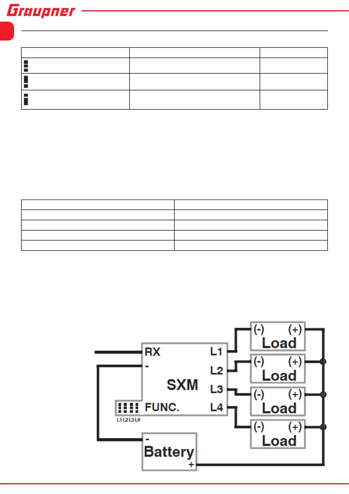
Receiver
connection
Technical features/function
-Switched functions and jumper positions for the four outputs L1 to L4:
Jumper position (FUNC.) Function Note
None (all pins open)
On/Off (memory) For L1 to L4
Top (centre pin to top pin)
Memory switch On/Off Only for L2 and L4
Bottom (centre pin to bottom
pin)
Flashing light On/Off (memory) L1 and L2 at 1Hz
L3 and L4 at 2Hz
• Select the desired function for each output L1 to L4, referring to the table above, before
switching the SXM on.
• When the SXM is switched on, all switched functions are always disabled, i.e. OFF.
• The switching contact connects (ON) or disconnects (OFF) the terminals (L1 to L4) of the
selected function to (-).
• If the control for the channel to which the SXM is connected (RX) is moved as in the table
below, the switched functions for L1 to L4 are activated or disabled.
Channel movement Switched function
- (Negative) less than about 0,75 seconds L1
- (Negative) more than about 0,75 seconds L2
+ (Positive) less than about 0,75 seconds L3
+ (Positive) more than about 0,75 seconds L4
• To minimise the risk of the unit switching on or off accidentally, a further switching process
cannot take place until the control for that channel is moved back in the direction of neutral
by a significant amount.
• When the function is changed by the jumper, the module and the receiver must be pow-
ered off. Only then the change is stored in the module!
 Loading...