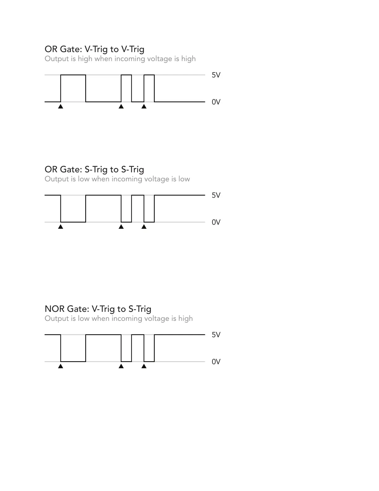
In the diagram above, black triangles indicate the onset of an incoming 0>5V signal.
With the OR gate active, input equals output: when input is high, output is high. This is
the most common application of Binary, and works with most modern devices.
The OR gate is also used when S-Trig signals should pass through without being
negated. S-Trig outputs are normally high, so the logic output of Binary will remain
high when S-Trig sources are patched to the inputs. The output will fall when the input
falls, correlating to an active gate/trigger from an S-Trig device, and signals will pass
through the circuit without being negated.
Things get a bit more interesting when you want to send V-Trig signals to a device with
an S-Trig input. To make this conversion, choose the NOR gate. Now the baseline
output is 5V (the “off” state of an S-Trig circuit). V-Trig input pulses will be negated,
dropping the output level to 0V, which is the “on” state of an S-Trig circuit. When the
V-Trig input pulse goes low, the output goes high again. No offset is needed.
 Loading...