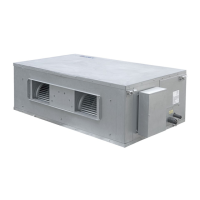
Multi Variable Air Conditioners Ducted Type Indoor Unit
14
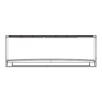
4.4.3 Installation of the Return Air Duct
(1) The default installation location of the rectangular flange is at the back and the return air
cover plate is at the bottom, as shown in Fig 4.4.6.
Fig 4.4.6
(2) If the bottom return air is desired, just change the rectangular flange with the return air
cover plate.
(3) Connect one end of the return air duct to the return air outlet of the unit with rivets and the
other to the return air louver. Use reinforced canvas duct for easy adjustment of duct.
(4) More noise is likely to be produced in the bottom return air mode than the rear return air
mode, install a silencer and a static pressure box to minimize the noise.
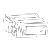
(5) Choose the best installation method by considering the building conditions and
accessibility needed maintenance etc., as shown in Fig 4.4.7.
Fig 4.4.7
Table 5 Installation of the return air duct
Return Air Inlet (with filter)
4.4.4 Installation of the Fresh Air Pipe
(1) When the fresh air pipe is needed to be connected, cut the fresh air baffle as Fig 4.4.8.
 Loading...