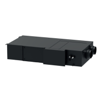
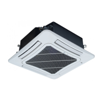
ERV+DX coil
16
Figure 3-1 Diagram for system electric wiring
NOTE!
Max indoor unit quantity n is according to the outdoor unit capacity. For more
details, please refer to the unit capacity configuration.
3.3.3 Selection of Communication Wire
(1) Selection of wired controller communication wire
Figure 3-2 Diagram of wired controller control connection

 Loading...


