GREE AIR SOURCE HEAT PUMP WATER HEATER SERVICE MANUAL
37
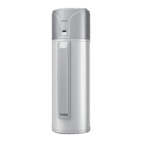
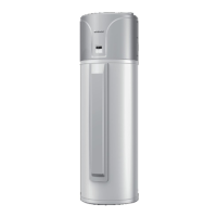
Figure 3-7 Installation sketch map of GRS-1.5/TD150ANbA-K; GRS-1.5/TD200ANbA-K
3.7 Installation Instruction of Wired Controller
(*GRS-2.4/D270ANbA-K)
(1) Fig. A is the standard installation way of wired controller. The wired controller is installed on the
unit before ex-factory;
(2) Fig. B is the detached installation way of wired controller. Long communication wire shall be
equipped to install the wired controller on the wall. If this kind of installation way is adopted, please contact
the after-sales installation personnel to select the communication cable with proper length;
Instructions for installing the wired controller on the wall:
① Remove the 6 fixing screws on the top cover;
② Remove the top cover;
 Loading...