80DWFK6HULHV'&
,QYHUWHU6HUYLFH0DQXDO
77
4.1.2 Connection between power cables and wiring terminals
Caution
%HIRUHLQVWDOOLQJWKHHOHFWULFDOHTXLSPHQWSOHDVHSD\DWWHQWLRQWRWKHIROORZLQJPDWWHUVZKLFK
KDYHEHHQVSHFLDOO\SRLQWHGRXWE\RXUGHVLJQHUV
&KHFNWRVHHLIWKHSRZHUVXSSO\XVHGFRQIRUPVWRWKHUDWHGSRZHUVXSSO\VSHFL¿HGRQWKHQDPHSODWH
7KHFDSDFLW\RIWKHSRZHUVXSSO\PXVWEHODUJHHQRXJK7KHVHFWLRQDUHDRI¿WWLQJOLQHLQWKHURRPVKDOO
be larger than 2.5mm
2
.
The lines must be installed by professional personnel.
An electricity leakage protection switch and an air switch with gap between electrode heads larger than
PPVKDOOEHLQVWDOOHGLQWKH¿[HGOLQH
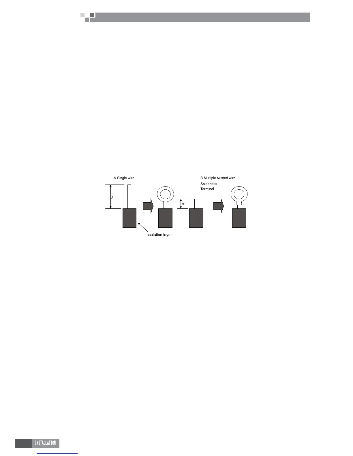
a. Connection of single wire
Ɣ
Use wire stripper to strip the insulation layer (25mm long) from the end of the single wire.
Ɣ
Remove the screw at the terminal board of the air-conditioning unit.
Ɣ
User pliers to bend the end of the single wire so that a loop matching the screw size is formed.
Ɣ
3XWWKHVFUHZWKURXJKWKHORRSRIWKHVLQJOHZLUHDQG¿[WKHORRSDWWKHWHUPLQDOERDUG
b. Connection of multiple twisted wires
Ɣ
Use wire stripper to strip the insulation layer (10mm long) from the end of the multiple twisted wires.
Ɣ
Remove the screw at the terminal board of the air-conditioning unit.
Ɣ
Use crimping pliers to connect a terminal (matching the size of the screw) at the end of the multiple
twisted wires.
Ɣ
3XWWKHVFUHZWKURXJKWKHWHUPLQDORIWKHPXOWLSOHWZLVWHGZLUHVDQG¿[WKHWHUPLQDODWWKHWHUPLQDO
board.
Warning:
,IWKHSRZHUVXSSO\ÀH[LEOHOLQHRUWKHVLJQDOOLQHRIWKHHTXLSPHQWLVGDPDJHGRQO\XVHVSHFLDOÀH[LEOH
line to replace it.
Before connecting lines, read the voltages of the relevant parts on the nameplate. Then carry out line
connection according to the schematic diagram.
The air-conditioning unit shall have special power supply line which shall be equipped with electricity
leakage switch and air switch, so as to deal with overload conditions.
The air-conditioning unit must have grounding to avoid hazard owing to insulation failure.
$OO¿WWLQJOLQHVPXVWXVHFULPSWHUPLQDOVRUVLQJOHZLUH,IPXOWLSOHWZLVWHGZLUHVDUHFRQQHFWHGWRWHUPLQDO
board, arc may arise.
All line connections must conform to the schematic diagram of lines. Wrong connection may cause
abnormal operation or damage of the air-conditioning unit.
Do not let any cable contact the refrigerant pipe, the compressor and moving parts such as fan.
Do not change the internal line connections inside the air-conditioning unit. The manufacturer shall not
be liable for any loss or abnormal operation arising from wrong line connections.
4.1.3 Power Cable Connection
a. Air-conditioning unit with single-phase power supply
Ɣ
Remove the front-side panel of the outdoor unit.
Ɣ
Pass the cable though rubber ring.
Ɣ
&RQQHFWWKHSRZHUVXSSO\FDEOHWRWKH³/1´WHUPLQDOVDQGWKHJURXQGLQJVFUHZ
Ɣ
8VHFDEOHIDVWHQHUWREXQGOHDQG¿[WKHFDEOH
b. Air-conditioning unit with 3-phase power supply
Ɣ
Remove the front-side panel of the outdoor unit.
Ɣ
Attach rubber ring to the cable-cross hole of the outdoor unit.
Ɣ
Pass the cable though rubber ring.
Ɣ
&RQQHFWWKHSRZHUFDEOHWRWKHWHUPLQDODQGHDUWKLQJVFUHZVPDUNHG³///1´
Ɣ
8VHFDEOHIDVWHQHUWREXQGOHDQG¿[WKHFDEOH
Ɣ
Caution:
 Loading...