82
Installation and Maintenance
Service Manual
Step Procedure
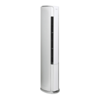
1. Before disassemble
2. Remove lter sub-assy
(1) Open the screw cover, use the screwdriver to
remove 2 screws at both sides of air-in panel and then
pull the air-in panel to remove it;
(2) Draw out the lter sub-assy.
3. Remove electric box and wire-passing groove
sub-assy
Remove 4 screws used for xing the electric box cover,
remove the electric box cover and then pull out the
wiring terminals for each component.
At this time, you can remove related electric
components according to the needs;
Remove 9 screws used for xing the electric box, pull
the electric box outwards to remove it.
Remove 3 screws used for fixing the wirepassing
groove, and then remove the wirepassing groove cover.
Remove 3 screws used for fixing the wirepassing
groove and then remove the wirepassing groove sub-
assy.
Caution: discharge the refrigerant
completely before removal.
Filter sub-assy
Air-in panel
Screw cover
Electric box cover
Electric box
Wire-passing
groove cover
Wire-passing groove
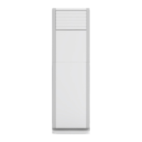
AL model
11. Removal Procedure
 Loading...