47
Installation and Maintenance
Service Manual
"Test point NO." Test point Related elements Test value under normal condition
Test 1 Between A and C Neutral wire ,live wire 160V-265V
Test 2 Between B and C Neutral wire ,live wire 160V-265V
Test 3 Between D and E Electrolytic capacitor of DC bas bar DC 180V-380V
Test 4 Between F and G Electrolytic capacitor of switch power DC 180V-380V
Test 5 Both ends of diode D59 D59(IPM module +15V) DC 14.5V-15.5
Test 6
Both ends of electrolytic
capacitor C47
C47(+12V power) DC 12V-13V
Test 7
Both ends of electrolytic
capacitor C60
C60(+5V power) DC 5V
Test 8
Both ends of electrolytic
capacitor C73
C73(+3.3V power) DC 3.3V
Test 9 Between S and T Communication circular current DC 56V
Test 10 Between point N and GND
C50 to N terminal (ground) (signal receiving terminal of
outdoor unit)
Jumping between 0V and 3.3V
Test 11 U7 Between 1 and 2 at leading foot of U7 Jumping between 0V and 3.3V
Test 12 Between point M and GND
R77 to N terminal (ground) (signal receiving terminal of
outdoor unit)
Jumping between 0V and 3.3V
Test 13 U8 Between 3 and 4 at leading foot of U8 Jumping between 0V and 3.3V
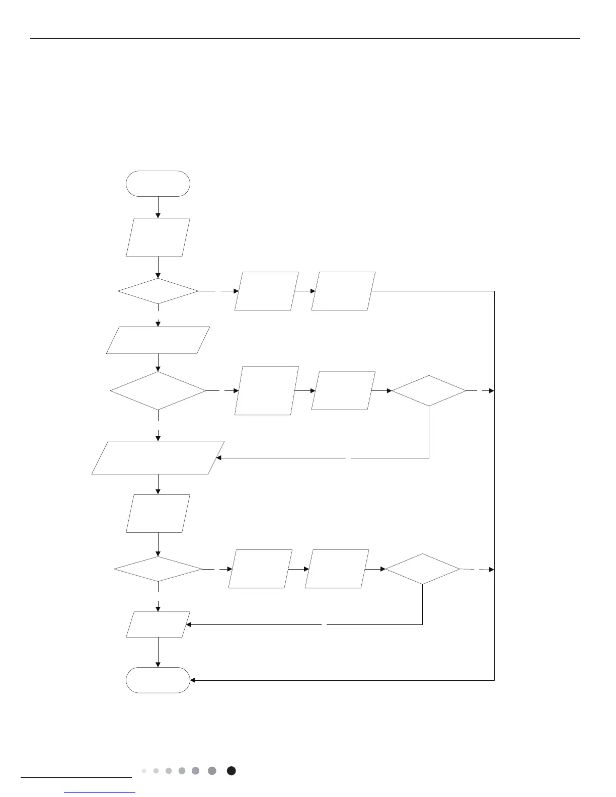
1.Capacity charging malfunction (outdoor unit malfunction) (AP1 below is control board of outdoor unit)
Main detection point:
● Detect if the voltage of L and N terminal of wiring board is between 210AC-240AC by alternating voltage meter;
● Is reactor (L) well connected? Is connection wire loosened or pull-out? Is reactor (L) damaged?
Malfunction diagnosis process:
N
Y
N
Y
N
Y
N
Y
N
Y
Turn on the unit
and wait 1 minute
Use DC voltmeter
to measure the
voltage on the two
ends of electrolytic
capacitor
Voltage higher than 200V?
Fault with the voltage
testing circuit on
control panel AP1
Replace the control
panel AP1
Measure the AC voltage between
terminal
L and N on wiring board
XT(power supply)
Voltage within
210VAC~250VAC?
Shut down the power
and repair the power
supply to restore the
range
210VAC~250VAC
power on and
restart the unit
If the fault is
eliminated?
Shut down the power and wait 20 mi
nutes; or
use DC voltmeter to measure the voltage
on the two ends of capacitor (test3), until
the voltage is lower than 20V
Check the
connection of reactor
(L in the Electrical
Wiring Diagram)
If the wiring of
reactor L
is normal?
Connect the reactor
Laccording to Elec-
trical Wiring Diagr-
am correctly
Re-energize and
turn on the unit
If the fault is
eliminated?
End
Replace the control
panel AP1
 Loading...