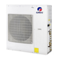
Do you have a question about the Gree GWHD(24)NK3GO and is the answer not in the manual?
Provides a brief overview of the outdoor unit models covered in the manual.
Diagrams showing the electrical connections for different models, crucial for installation and troubleshooting.
Printed circuit board layouts with component identification for reference.
Details the system's operation in Cooling, Dry, Heating, and Fan modes.
Describes various protection mechanisms like mode conflict, overload, and temperature protections.
Covers refrigerant recovery and master/slave unit settings.
Covers electrical, refrigerant, and general safety guidelines for installation and maintenance.
Lists necessary tools for performing installation and maintenance tasks.
Step-by-step instructions for installing the air conditioning system.
Provides a flowchart of the overall installation process from start to finish.
Details how to connect the power cord and air switch for different models.
Guides on selecting location, securing the unit, connecting pipes, and vacuum pumping.
Illustrates the physical dimensions and required clearances for outdoor units.
Lists checks to perform after installation to ensure proper function and safety.
Provides detailed guidance on selecting optimal locations for indoor and outdoor units.
Details the importance and methods of proper earthing for electrical safety.
Specific considerations and procedures for installing the outdoor unit.
Covers noise reduction during installation and lists required accessories.
Details on connecting indoor and outdoor units, including wiring and pipe configurations.
Instructions for connecting the power cord to the unit and ensuring proper wiring.
Covers pipe dimensions, torque specifications, and installation methods.
Essential steps for charging refrigerant and performing initial operational tests.
Details on calculating and adding refrigerant charge for optimal performance.
Lists items to check for secure installation and proper function.
Procedure for conducting the initial operational test of the installed unit.
Critical safety steps before servicing, emphasizing capacitor discharge.
Explains LED indicators and how to view malfunction codes for diagnosing issues.
Detailed troubleshooting steps and flowcharts for resolving various system malfunctions.
Lists error codes and provides flowcharts for diagnosing and resolving malfunctions.
Offers solutions for common issues like unit not starting, poor cooling/heating, and abnormal sounds.
Provides a reference table for converting Celsius to Fahrenheit temperatures.
Explains pipe configuration, length limits, and refrigerant charging based on pipe size.
Details the steps for expanding pipes correctly to prevent refrigerant leaks.
Lists resistance values for ambient temperature sensors at various temperatures.
| Refrigerant | R410A |
|---|---|
| Indoor Unit Dimensions (W x H x D) | 845 x 290 x 200 mm |
| Outdoor Unit Dimensions (W x H x D) | 870 x 635 x 340 mm |
| Weight (Outdoor Unit) | 42 kg |
| Type | Split System |
| Outdoor Unit Weight | 42 kg |
| Power Supply | 220-240V, 50Hz |
| Cooling Capacity | 24000 BTU/h |


