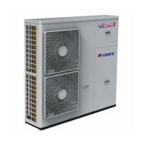
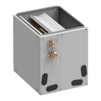
GREE COMMERCIAL AIR CONDITIONERS AIR-TO-WATER HEAT PUMP
CONTENTS
PRODUCT ..............................................................................................................................................1
1 MODELS LIST .................................................................................................................................1
1.1 Main Unit ..................................................................................................................................1
1.2 Water Tank ...............................................................................................................................2
2 NOMENCLATURE ..........................................................................................................................2
2.1 Main Unit ..................................................................................................................................2
2.2 Water Tank ...............................................................................................................................3
3 FUNCTION.......................................................................................................................................3
3.1 Cooling .....................................................................................................................................3
3.2 Heating .....................................................................................................................................3
3.3 Water Heating..........................................................................................................................3
3.4 Cooling +Water Heating.........................................................................................................3
3.5 Heating+ Water Heating.........................................................................................................4
3.6 Emergency Mode....................................................................................................................4
3.7 Quick Water Heating ..............................................................................................................4
3.8 Holiday Mode...........................................................................................................................4
3.9 Forced Operation Mode.........................................................................................................4
3.10 Silent Mode............................................................................................................................4
3.11 Disinfection Mode .................................................................................................................4
3.12 Weather-dependent Heating Mode....................................................................................4
4 PRODUCT DATA .............................................................................................................................5
4.1 Product Data at Rated Condition..........................................................................................5
4.2 Operation Range.....................................................................................................................9
4.3 Electrical Data .......................................................................................................................10
5 PIPING DIAGRAM ........................................................................................................................ 11
UNITS CONTROL...............................................................................................................................12
1 OPERATION FLOWCHART.......................................................................................................... 12
2 MAIN LOGIC .................................................................................................................................12
2.1 Defrosting Mode....................................................................................................................12
2.2 Water-side Auto Anti-freezing in Winter.............................................................................13
2.3 Control of Heating Tape on Chassis...................................................................................13
2.4 Control of Fan........................................................................................................................13
2.5 Control of Compressor.........................................................................................................13
2.6 Control of Electric Expansion Valve ...................................................................................13
3 WIRED CONTROLLER.................................................................................................................14
3.1 Dimension ..............................................................................................................................14
3.2 Function..................................................................................................................................14
3.3Installation ...............................................................................................................................62
4 CONTROL WIRING DESIGN .......................................................................................................64
INSTALLATION ...................................................................................................................................65
1 INSTALLATION OF UNITS .......................................................................................................... 65
1.1 Installation Positions.............................................................................................................65
1.2 Matters Need Attention.........................................................................................................66
1.3 Dimension Data.....................................................................................................................66
1.4 Installation Clearance Data .................................................................................................75
1.5 Connection of Pipeline .........................................................................................................80
2 ELECTRIC WIRING WORK.......................................................................................................... 83
2.1 Wiring Principle .....................................................................................................................83
2.2 PCB Outline ...........................................................................................................................84
2.3 Electric Wiring Design ..........................................................................................................88
UNITS MAINTENANCE....................................................................................................................102
1 ERROR CODE LIST..................................................................................................................... 102
2 FLOW CHART OF TROUBLESHOOTING................................................................................. 108
3 DIAGNOSIS OF DRIVING.......................................................................................................... 112
3.1 Diagnosis Flowchart of Driving of Single-phase Unit ....................................................113
3.2 Diagnosis Flowchart of Driving of Three-phase Unit .....................................................120
METHOD OF TESTING IPM MODULE SHORT CIRCUIT: ........................................................121
4 DISASSEMBLY AND ASSEMBLY PROCEDURE OF MAIN PARTS ....................................... 128
5 EXPLODED VIEWS AND PART LIST........................................................................................ 145
5.1 Outdoor Exploded View and Part List..............................................................................145
5.2 Indoor Exploded View and Part List .................................................................................153
5.3 Water Tank Exploded View and Part List ........................................................................159

 Loading...
