33
Air to Water Heat Pump
Service Manual- Versati II Series
CONTROL
3�3�6 Key Lock
At the homepage, by pressing the Up/Down keys simultaneously for 5 seconds, it is able to activate or
deactivate this function. When it is activated, any key operation is ineffective.
3�4 Precautions
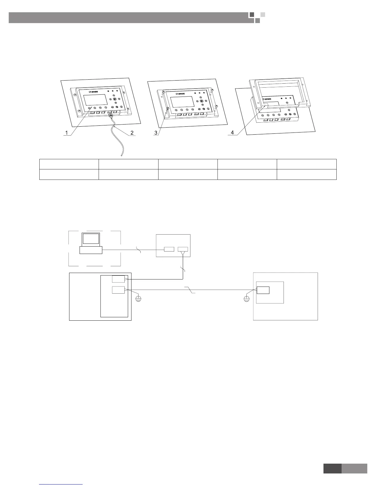
Install the control following instruction shown in the gure below.
No� 1 2 3 4
Name LCD Communication line Screws ST4.2X16 Rubber pad
Installation Steps
Step 1: draw the communication lines out from the LCD
Step 2: take four screws away from the rubber pad.
Step 3: remove the rubber pad off the LCD.
(3) After LCD is removed, unplug communication line according Fig 4.
4 CONTROL WIRING DESIGN
Installation Instruction :
(1) Wired controller connects to terminal CN6 on mainboard of indoor unit by 4-core communication line.
(2) The indoor unit connects to outdoor unit by 3-core communication line. Wiring terminal of indoor unit is
CN5 and that of the outdoor unit is CN66.
(3) Remote monitoring device connects to terminal CN4 of Display Board by 4-core communication line.

 Loading...