Alfaspid RAS, BIG RAS, REAL
Azimuth - Use SETUP->OPTION = SPID
Elevation – Use SETUP ->OPTION = SPID
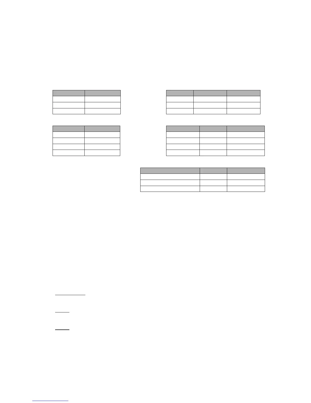
DC Motor Transformer Taps
Jumper Position Transformer
J5 2-3 MOT CW 1 2
J6 2-3 MOT CCW 2 1
J16 1-2 GND 3 3
POS(Position) 4 4
Sensor Connections Hi Res only
These sensor connections for Hi Res are used instead of the terms 3
and 4 connections that are utilized with the Standard SPID
CALIBRATION PROCEDURE
1. Verify that your rotor is 1 pulse/degree (Pulse Divider = 360) which is the standard
number for the RAS and REAL. The Big RAS typically is ½ degree resolution for a
Pulse divisor requirement of 720. Some units have other divisors, and the High
Resolution versions should be 2880. The RT-21 supports all versions, contact us if
you need assistance determining your correct Divider value.
2. The azimuth rotors have no limit switches, so be certain you do not over-travel beyond
the limits of your rotor loops!!!! Adjust the antenna position on the mast or turn with the
CW or CCW buttons until the antenna is at some physical known heading or elevation.
The elevation rotators do contain limit switches to contain rotation to 180 degrees.
3. Go to SETUP/CALIBRATE and match the displayed heading with the visual, actual
heading or elevation into the “NEW VALUE = “ by turning the front panel knob.
IMPORTANT: Insure that your coax loop around the rotator will support your rotating
range. The Alfa Spid has no internal limit switches on the azimuth rotator.
NOTE: If you rotator turns backwards, simply swap the motor wires between terminals
1 & 2.
NOTE: If your indicator shows ½ of the actual travel (you turn it 10 degrees on the
indicator and the antenna actually turns 20), then change the Pulse Divider to
720.
Function SPID RT-21
IN IMP 1 (or IN IMP2) 3 (or 2) 4
12 VDC (for Sensor Power) 6 and 7 5
GND (for Sensor) 8 and 9 3
 Loading...