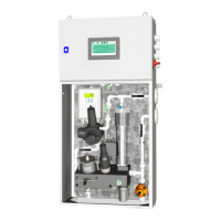
Water Monitoring System
Ver.5.0.1 – Revision August 2022 Page 5 of 111
List of Figures
Figure 1-1: Program Menu Structure of the Water Monitoring System ........................................................2
Figure 4-1: Menu Structure ......................................................................................................................... 18
Figure 4-2: Home Page ............................................................................................................................... 19
Figure 4-3: G6110/G6111 PAH Low Range ............................................................................................... 20
Figure 4-4: G6110/G6111 PAH High Range ............................................................................................... 20
Figure 4-5: G6110 PAH Dual Range in Operation Mode ........................................................................... 20
Figure 4-6: G6110 Dual Range - Low Range during Calibration ............................................................... 21
Figure 4-7: G6110 Dual Range - High Range during Calibration ............................................................... 21
Figure 4-8: G6111 PAH Dual Range ........................................................................................................... 21
Figure 4-9: Turbidity Page .......................................................................................................................... 21
Figure 4-10: Settings Page .......................................................................................................................... 22
Figure 4-11: Setup Page .............................................................................................................................. 23
Figure 4-12: Timer Setup Page ................................................................................................................... 23
Figure 4-13: Signal Setup Page - Low Range PAH Setting ........................................................................ 24
Figure 4-14: Signal Setup Page - Flow Setting ........................................................................................... 24
Figure 4-15: Alarm Page ............................................................................................................................. 25
Figure 4-16: Logging Page for Exporting the Logged Data ........................................................................ 26
Figure 4-17: System Info Page .................................................................................................................... 26
Figure 4-18: Trend Page .............................................................................................................................. 29
Figure 4-19: Trend PAH Page ..................................................................................................................... 29
Figure 6-1: pH Validation/Calibration Procedure........................................................................................ 36
Figure 6-2: PAH Validation/Calibration Procedure ..................................................................................... 39
Figure 6-3: G6110 PAH sensor, measuring chamber & calibration chamber & bushing & bushing tool ... 42
Figure 6-4: PAH Chamber Bushing Placement ........................................................................................... 42
Figure 6-5: G6111 PAH Sensor, PAH measuring Chamber & PAH calibration Chamber .......................... 43
Figure 6-6: G6110 PAH sensor, measuring chamber & calibration chamber & bushing & bushing tool ... 45
Figure 6-7: PAH Chamber Bushing Placement ........................................................................................... 45
Figure 6-8: G6111 PAH Sensor, PAH measuring Chamber & PAH calibration Chamber .......................... 46
Figure 8-1: Planned Maintenance Program for the Water Monitoring System ........................................... 53
Figure 9-1: Wire connections for Emitter, Receiver and Wiper Unit .......................................................... 56
Figure 9-2: Squeezing the Hose .................................................................................................................. 58
Figure 12-1: mA Measurement using Multimeter – G6111 PAH Sensor .................................................... 67
Figure 12-2: pH Negative offset - Reading Too Low .................................................................................. 70
Figure 12-3: pH Positive Offset – Reading Too High ................................................................................. 70

 Loading...