EasyManua.ls Logo

GreenBrook DHT01A-C User Manual

GreenBrook DHT01A-C
1 page
Page #1 background imageLoading...
Page #1 background image
Diagram 1
Do not mount chime on door
1. Remove front cover by unscrewing the
small screw at the base of cover.
2. Feed bell-push wire into top of chime
base and connect to terminals 0 and 2.
3. Remove transformer cover (Dia 3).
4. Feed 230V mains Supply cable into the
bottom of the chime base (Dia 2)
5. Connect the Live (Brown) wire to
the”L” terminal and the Neutral (Blue)
wire to the “N” terminal (Dia 3)
SWITCH OFF THE MAINS AND
ISOLATE THE SUPPLY BY REMOVING THE
APPROPRIATE FUSE BEFORE STARTING
THE INSTALLATION
6. Replace the transformer cover and
front cover.
7. Test unit by pushing bell push.
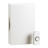
INSTRUCTIONS FOR USE
DOORCHIME WITH BUILT-IN
TRANSFORMER AND BELL PUSH
MODEL NUMBER: DHT01A-C
Dual tone chime
Powered by internal transformer
Bellpush and woodscrews are supplied
Diagram 3
Recommended maximum overall
length of bell wire for doorchime
with built-in transformer:
SWG 21 (0.5mm
2
) - 30 metres
SWG 19 (0.75mm
2
) - 45 metres
PLEASE KEEP THESE
INSTRUCTIONS SAFE
FOR FUTURE REFERENCE
Issue number: 701403
Diagram 2
West Road, Harlow,Essex
CM20 2BG
E mail gbe@greenbrook.co.uk
Web page www.greenbrook.co.uk
Question and Answer IconNeed help?

Do you have a question about the GreenBrook DHT01A-C and is the answer not in the manual?

GreenBrook DHT01A-C Specifications

General IconGeneral
Measurement Range (Humidity)20% to 90% RH
Accuracy (Humidity)±5% RH
Resolution (Humidity)1% RH
TypeDigital Humidity and Temperature Sensor
Contact TypeN/A (Digital Sensor)

Summary

DoorChime Installation and Safety Precautions

Switch Off Mains Supply

Ensure the mains supply is switched off and isolated by removing the appropriate fuse before starting installation.

Remove Front Cover

Remove the front cover by unscrewing the small screw located at the base of the cover.

Connect Bell-Push Wire

Feed the bell-push wire into the top of the chime base and connect it to terminals 0 and 2.

Feed Mains Supply Cable

Feed the 230V mains supply cable into the bottom of the chime base as shown in Diagram 2.

Connect Live and Neutral Wires

Connect the Live (Brown) wire to the 'L' terminal and the Neutral (Blue) wire to the 'N' terminal.

Replace Covers and Test Unit

Replace the transformer cover and front cover, then test the unit by pushing the bell push.

Mounting Guidelines and Specifications

Do Not Mount Chime on Door

Visual guidance illustrating that the chime unit should not be mounted directly onto a door.

Recommended Bell Wire Lengths

Specifies maximum recommended bell wire lengths for the doorchime with built-in transformer.