RV and RVE Quick Start Guide, Rev. 4, October 2019
17. Verify operation and rotation of all condensing fans.
a. Check that the fan blade doesn't contact the guard around the fan impeller.
b. Check amperage of condensing fans while running and ensure they are below FLA. Contact Greenheck techni-
cal support if this is not the case.
18. Allow the cooling system to run unimpeded for 10-15 minutes while system stabilizes.
19. Measure Circuit A’s subcooling. (Record in *Start-up Report, including changes you make).
a. Proper subcooling is 10-12°F.
b. If subcooling is below 10°F and sight glass is not clear, add refrigerant to obtain 10-12°F subcooling.
c. If subcooling is above 12°F, remove refrigerant to obtain 10-12°F subcooling.
20. Measure Circuit A’s superheat. (Record in *Start-up Report, including changes you make).
a. Proper superheat is 7-9°F.
b. If superheat is below 7°F, adjust the TXV clockwise.
c. If superheat is above 9°F, adjust the TXV counter-clockwise.
21. If circuit is equipped with hot gas reheat, change the reheat percentage to 100% for 5 minutes (reference step 15).
22. Measure the circuit subcooling. (Record in *Start-up Report, including changes you make).
a. Proper subcooling is 10-12°F.
b. If subcooling is below 10°F and sight glass is not clear, add refrigerant to obtain 10-12°F subcooling.
c. If subcooling is above 12°F, remove refrigerant to obtain 10-12°F subcooling.
23. Measure the circuit superheat. (Record in *Start-up Report, including changes you make).
a. Proper superheat is 7-9°F.
b. If superheat is below 7°F, adjust the TXV clockwise.
c. If superheat is above 9°F, adjust the TXV counterclockwise
24. Change the reheat percentage to 0% and repeat steps 18-20.
25. Measure and record the compressor amp draw and compare to nameplate FLA.
(Record in *Start-up Report, including changes you make).
Heating Start Up (If heating components are present)
1. Press the program key.
2. Scroll down to Ctrl Variables, press enter key.
3. Scroll down to Advanced, press enter key.
4. Scroll down to Login, enter 9998 as password for service level access. Should then automatically back out of the
login screen.
5. Scroll down and enter the Manual Overrides menu.
6. Press the down key once, and the controller will prompt you to press enter to begin IG furnace commissioning.
7. Press enter on this screen; You have now entered furnace commissioning.
Furnace Commissioning
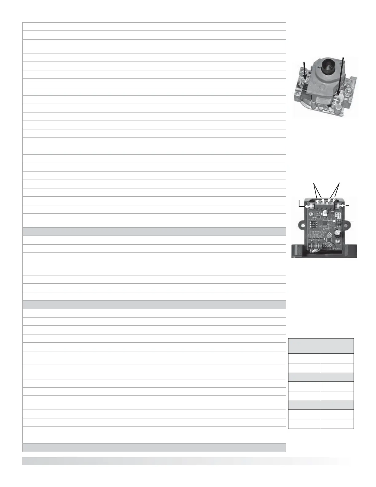
1. Adjust outlet pressure on the combination valve.
a. Connect manometer to outlet pressure tap on combination valve. See Figure 4
b. Adjust outlet pressure using outlet pressure adjustment screw. See Figure 4
2. Adjust the High Fire setting on the modulating valve.
a. Connect manometer to test port on burner manifold.
b. Press and hold button #1 until the LED lights solid red on the modulating valve. Release button and observe
pressure on manometer. See Figure 5
c. Adjust modulating valve by pushing button #1 to increase the pressure and button #2 to decrease the pressure.
See Figures 5 & 6
d. Save the High Fire setting by simultaneously pressing button #1 and #2 until the LED turns off.
3. Adjust Low Fire setting on mod valve
a. Press and hold button #2 until LED blinks RED. Release button and observe pressure on manometer.
See Figure 5
b. Adjust low fire setting by pushing button #1 to increase or button #2 to decrease the pressure. See Figures 5 & 6
c. Save the Low Fire setting by simultaneously pressing button #1 and #2 until the LED turns off.
4. Repeat steps 2 and 3 for high turndown furnaces.
5. Continue through commissioning menu to verify proper furnace operation.
CUSTOMER SUPPORT 1-866-478-2574.
Figure 6:
Gas Pressure Settings
Natural Gas 5 in. wg
LP Gas 11.5 in. wg
High Fire Settings
Natural Gas 3.5 in. wg
LP Gas 10.0 in. wg
Low Fire Settings
Natural Gas 0.3 in. wg
LP Gas 1.0 in. wg
Figure 5:
EXA Modulating Gas Valve
(with cover removed)
Terminals
3 & 4
(power)
Button #2
Low Fire
Adjust
LED
Light
Button #1
High Fire
Adjust
Terminals
1 & 2
(signal)
Combination Valve/
Outlet Pressure
Adjustment
Figure 4: Combined Regulator
Valve
Outlet
Pressure
Tap
Copyright 2019 © Greenheck Fan Corporation
 Loading...